2
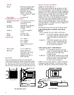
1-25/32"
(45mm)
1-25/32"
(45mm)
Panel Cutout
Panel
3 3/8"
(86mm)
3 3/4"
(95mm)
Mounting Bracket
SPADE TONGUE
CONNECTOR FOR
NO. 6 STUD
3/8"
5/16"
9/16"
20 Ga. Wire
Mounting Dimensions
Lead Termination
MANUAL RESET ADJUSTMENT
(Applies to the ETR-905 only.)
When the process stabilizes, approximately one half
hour after adjusting set point, an adjustment in “reset”
may also be necessary. Start with the reset adjustment
pointing to zero. If the temperature indication stabilizes
above the set point temperature, then adjust the reset
to the “minus” side. If the temperature indication
stabilizes below the set point temperature, then adjust
to the “plus” side. By turning this adjustment once or
more, the indicated temperature should eventually
match the set point temperature. It is very important to
wait approximately 15 minutes after each adjustment to
allow the system to stabilize.
WIRING
All wiring should conform to local and national codes:
Following Diagrams for ETR-901 and ETR-902
Models:
(Do not operate 120 volt controls on 240 volts.)
Diagram 1:
For 120VAC operation and relay output.
An external magnetic contactor must be
used if the heater load exceeds 360
watts.
Diagram 2:
For 120VAC operation and 3-32VDC
output. For use with solid-state relay
for heater control. Solid-state relays
can be single or three-phase.
Following Diagrams for ETR-905 Model:
Diagram 3:
For 90-264VAC operation and relay
output. An external magnetic contactor
must be used if the heater load
exceeds 3 amps.
Diagram 4:
For 90-264VAC operation and 3-32VDC
output. For use with a solid-state relay
for heater control. Solid-state relays
can be single or three-phase.
NOTE: The use of motor starters in place of magnetic
contactors should be avoided. They have very large
inductive loads that can damage the controller’s relay.
POWER
Rating:
ETR-901 and 902 models
110/220VAC NOT field
selectable ±15%, 50/60Hz.
ETR-905 model 90-
264VAC. 24V AC/DC
models available on special
order.
Consumption:
Less than 3VA.
ENVIRONMENTAL & PHYSICAL
Operating Temperature: 10° to 125°F (-12 to 52°C).
Humidity:
10 to 90% RH (non-
condensing).
Insulation:
20M ohm Min, (5000VDC).
Breakdown:
2000VAC, 50/60Hz,
1 minute.
Vibration:
10 - 55Hz, Amplitude
1.0mm.
Shock:
660 ft./S
2
(20g).
Weight:
9 oz. (250 grams)
DIMENSIONS
H 1
7
⁄
8
” (48mm)
W 1
7
⁄
8
” (48mm)
D 3
3
⁄
4
” (95mm)
Depth behind panel 3
3
⁄
8
”
(86mm)
Panel Cutout:
1
25
⁄
32
” sq. (45mm sq.)
DIN Case:
Plastic, full plug-in
construction, with screw
terminals on rear,
adjustable brackets for
panel mounting.
MOUNTING
When mounting the instrument, it is important the
control remains within the ambient temperature range
of 10 to 125°F. Mounting it in any position is permissi-
ble. After inserting the control into the panel, secure it
with the two mounting brackets provided with each unit.


