TROUBLESHOOTING
Experience has proven that many control problems are
not caused by a defective instrument. See below for
some of the common causes of failures:
Line wires are improperly connected.
No voltage between line terminals
Incorrect voltage between line terminals.
Connections to terminals are open, missing or loose.
Thermocouple (or RTD) is open at tip.
Thermocouple (or RTD) lead is broken.
Shorted thermocouple (or RTD) leads.
Short across terminals.
Open or shorted heater circuit.
Open coil in external contactor.
Return Control to:
OGDEN MANUFACTURING CO.
ATTN: Repair Department
64 West Seegers Road
Arlington Heights, IL 60005
Telephone: (847) 593-8050 • FAX: (847) 593-8062
OGDEN and ETR are registered trademarks of Ogden Manufacturing Co.
Specifications subject to change without notice.
© Ogden Manufacturing Co. 2000
MARCA REGISTRADA
Burned out line fuses.
Defective line switches.
Burned out contactor.
Defective circuit breakers.
If these points have been checked and the controller still
does not function, it is suggested that the instrument be
returned for inspection.
Do not attempt to make repairs. Also, it is advisable to
use adequate packing materials to prevent damage in
shipment.
Printed in U.S.A. 3/01
1
2
3
4
5
6
7
8
9
10
+
-
(Red)
T/C
B
B
A
3 - Wire
RTD
•
o
o
o
o
120VAC
5A Fuse
Hot
Heater–
If less than 3A
Contactor Coil–
If more than 3A
C
N.O.
N.C.
1
2
3
4
5
6
7
8
9
10
+
(Red)
T/C
B
B
A
3 - Wire
RTD
•
o
o
o
o
120VAC
5A Fuse
Hot
1
2
3
4
+
Solid State
Relay
o
o
Heater Power
Heater Fuse
Heater(s)
+
–
–
1
2
3
4
5
6
7
8
9
10
+
-
(Red)
T/C
B
B
A
3 - Wire
RTD
•
o
o
o
o
90-260VAC
5A Fuse
Hot
Heater–
If less than 3A
Contactor Coil–
If more than 3A
C
N.O.
N.C.
1
2
3
4
5
6
7
8
9
10
+
(Red)
T/C
B
B
A
3 - Wire
RTD
•
o
o
o
o
90-260VAC
5A Fuse
Hot
1
2
3
4
+
Solid State
Relay
o
o
Heater Power
Heater Fuse
Heater(s)
+
–
–
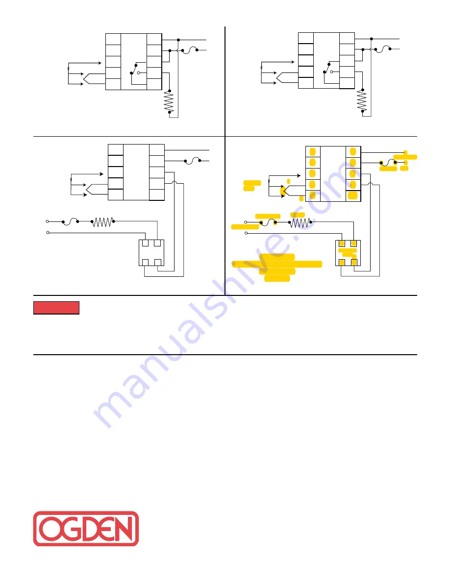
DIAGRAM 1
120V Operation for Heating
with Relay Output
ETR-901/902
NOTE: Other voltages can be used if the control was specified and labeled thus.
DIAGRAM 2
120V Operation for Solid-state
Relay Output
ETR-901/902
DIAGRAM 3
90-264V Operation for Heating
with Relay Output
ETR-905
DIAGRAM 4
90-264V Operation for Solid-state
Relay Output
ETR-905
Failure of devices, such as the thermocouple-RTD sensor, heater output relay or temperature control
can result in severe damage to a product while in process, melting of the heater or a damaging fire.
An over-temperature protection device must be installed in your process that will remove all power from the heating
circuit if the above failure occurs. We recommend that this device be classified as a safety control and carry U.L.,
CSA or FM listing or certification. Failure to install high-limit temperature control protection where a potential hazard
exists, could result in damage to equipment and property, and fatal injury to personnel.
WARNING!
NOTE: Other voltages can be used if the control was specified and labeled thus.


