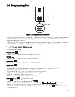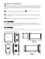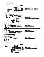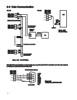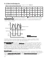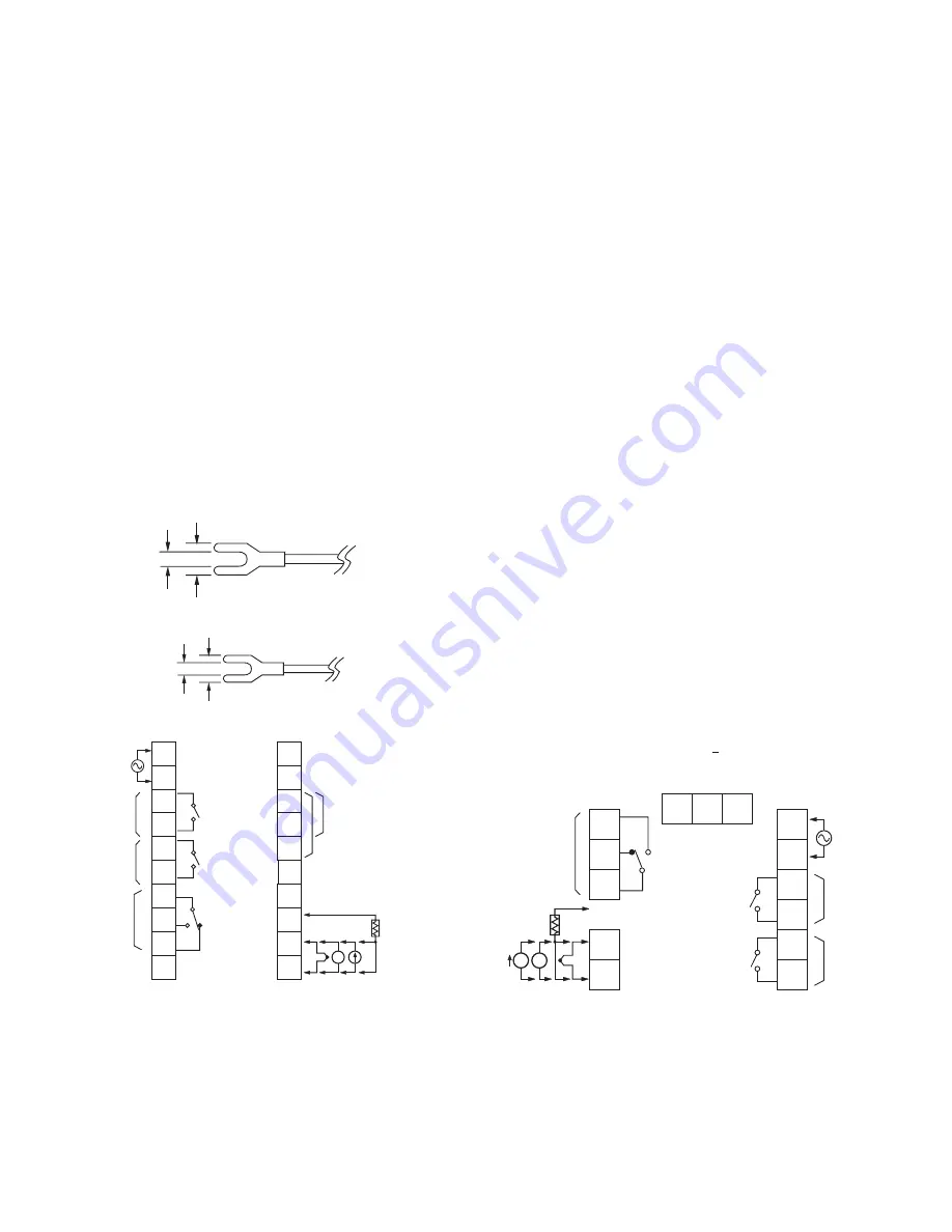
2 - 3 Wiring Precautions
Before wiring, verify the label for correct model number and options. Switch off the power while checking.
Care must be taken to ensure that the maximum voltage rating specified on the label is not exceeded.
It is recommended that the power of these units be protected by fuses or circuit breakers rated at the lowest
value possible.
All units should be installed inside a suitably grounded metal enclosure to prevent live parts from contact with
human hands and metal tools.
All wiring must conform to appropriate standards of good practice and local codes and regulations. Wiring must
be suitable for voltage, current, and temperature rating of the system.
Beware not to overtighten the terminal screws. The torque should not exceed 1 N-m (8.9 Lb-in or 10.2 KgF-cm).
Unused control terminals should not be used as jumper points as they may be internally connected, causing
damage to the unit.
Verify that the ratings of the output devices and the inputs as specified in Chapter 6 are not exceeded.
Except the thermocouple wiring, all wiring should use stranded copper conductor with a maximum
gauge of 18 AWG.
*
*
*
*
*
*
*
*
*
14
1
2
3
4
5
6
7
8
9
13
12
11
14
15
16
17
18
19
20
90-250VAC
47-63 Hz
12VA
L
N
OP1
_
+
OP2
_
+
ALM
RS-485
RE+ TX1 TXD
B
B
A
RTD
_
_
+
+
V
_
+
PTA
TC+, V+
PTB, mA+
TC-, V-
PTB, mA-
TC
V mA RTD
10
C
NO
C
NO
NC
C
NO
RS-232
Figure 2.4 Rear Terminal Connection
for ETR-4100 and ETR-8100
Figure 2.4 Rear Terminal Connection
for ETR-4100 and ETR-8100
COM
50 C max. air ambient
Use copper conductors
(except on T/C input)
L
RE TX2 RXD
RETRANSMISSION
1
2
3
4
5
6
7
8
9
10
11
12
_
_
+
+
I
B
B
A
RTD
V
ALM
90-250VAC
47-63 Hz
12VA
L
N
C
NO
C
NO
C
NO
_
+
OP2
_
+
Figure 2.5
Rear Terminal Connection for ETR-9100
Figure 2.5
Rear Terminal Connection for ETR-9100
NC
13 14 15
RS-232:
TXD
TX1 TX2
RXD COM
RS-485:
OP1
PTA
TC+, V+
PTB, mA+
TC-, V-
PTB, mA-
50 C max. air ambient
Use copper conductors (except on T/C input )
L
RETRANSMISSION:
RE+ RE
Figure 2.3 Lead Termination
for ETR-9100
7.0mm max.
3.2mm min.
6.0mm max.
3.0mm min.
Figure 2.2 Lead Termination for
ETR-4100 and ETR-8100

