2-9 Data Communication
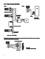
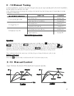
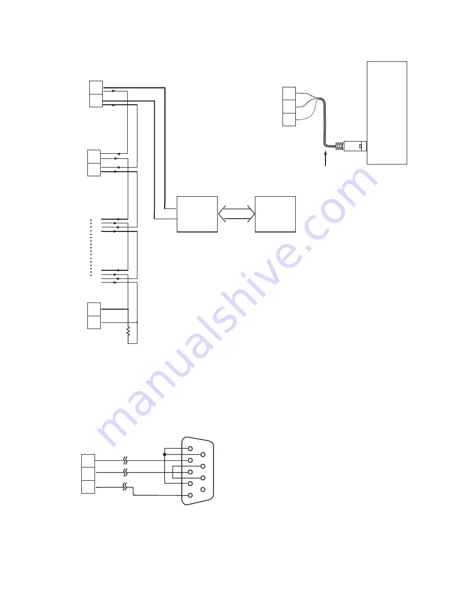
Figure 2.21 RS-485 Wiring
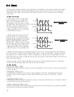
RS-232
PC
9-pin
RS-232
port
9-pin
RS-232
port
Figure 2.22
RS-232 Wiring
Figure 2.22
RS-232 Wiring
CC94-1
TXD
RXD
COM
13
14
15
1
2
3
4
5
6
7
8
9
TX1
RD
TX2
TD
COM
GND
Female DB-9
To DTE ( PC ) RS-232 Port
1 DCD
2 RD
3 TD
4 DTR
5 GND
6 DSR
7 RTS
8 CTS
9 RI
1 DCD
2 RD
3 TD
4 DTR
5 GND
6 DSR
7 RTS
8 CTS
9 RI
Figure 2.23
Configuration of RS-232 Cable
Figure 2.23
Configuration of RS-232 Cable
Using RS-232 communications as shown in fig. 2.2, a special cable CC-94-1 should be used. The other option is
to configure a 9-pin serial cable as in fig. 2-23.
Using RS-232 communications as shown in fig. 2.2, a special cable CC-94-1 should be used. The other option is
to configure a 9-pin serial cable as in fig. 2-23.
18
TX1
TX1
TX1
TX2
TX2
TX2
Terminating Resistor
220 ohms / 0.5W
Terminating Resistor
220 ohms / 0.5W
Max. 247 units can be linked
RS-232
SNA10A or
SNA10B
SNA10A or
SNA10B
RS-485 to RS-232
network adaptor
RS-485 to RS-232
network adaptor
Shielded Twisted-Pair Wire
13
14
TX1
TX2
13
14
ETR-4100
ETR-8100
ETR-9100
ETR-4100
ETR-8100
ETR-9100
RS-485
PC
ETR-4100
ETR-8100
ETR-9100
ETR-4100
ETR-8100
ETR-9100
13
14
ETR-4100
ETR-8100
ETR-9100
ETR-4100
ETR-8100
ETR-9100
ETR-4100
ETR-8100
ETR-9100
ETR-4100
ETR-8100
ETR-9100
TXD
RXD
COM
13
14
15
ETR-4100
ETR-8100
ETR-9100
ETR-4100
ETR-8100
ETR-9100

