28
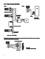
Two types of interfaces are available for Data Communication. These are RS-485 and RS-232 interface. Since RS-
485 uses a differential architecture to drive and sense signal instead of a single-ended architecture which is used for
RS-232, RS-485 is less sensitive to the noise and suitable for a longer distance communication. RS-485 can
communicate without error over 1 km distance while RS-232 is not recommended for a distance over 20 meters.
Using a PC for data communication is the most economical way. The signal is transmitted and received through the
PC communication Port (generally RS-232). Since a standard PC can't support RS-485 port, a network adaptor
(such as SNA10A, SNA10B) has to be used to convert RS-485 to RS-232 for a PC if RS-485 is required for the data
communication. Many RS-485 units (up to 247 units) can be connected to one RS-232 port, therefore a PC outfitted
with 4 comm ports can communicate with up to 988 units. Communications encompass a large scope of
applications from single point interface through hundreds of controls to historical trending through endless zones.
ETR communications provide for a very powerful and economic solution.
Setup
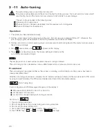
Enter the setup menu.
Select RTU for COMM. Set individual addresses for each unit which is connected to the same port.
Set the Baud Rate (BAUD), Data Bit (DATA), Parity Bit (PARI) and Stop Bit (STOP) such that these values are in
accordance with PC setup conditions.
If you use a conventional 9-pin RS-232 cable instead of CC94-1, the cable should be modified for proper operation
of RS-232 communication according to Section 2-9.
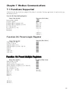
Please see Chapter 7 for more detailed information.
3-14 Data Communication
The controllers support RTU mode of Modbus protocol for the data communication. Other protocols are not available
for this series.
The controller can output (retransmit) process value via its retransmission terminals RE+ and RE- provided that the
retransmission option is ordered. A correct signal type should be selected for COMM parameter to meet the
retransmission option installed. RELO and REHI are adjusted to specify the low scale and high scale values of
retransmission.
3 -15 PV Retransmission
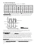
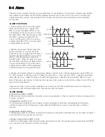
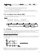
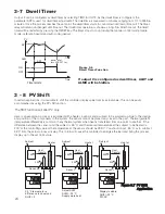
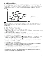
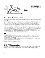
D action
PV
Time
Perfect
TD too high
TD too low
Set point
Figure 3.9 Continued
Effects of PID Adjustment
Figure 3.9 Continued
Effects of PID Adjustment


