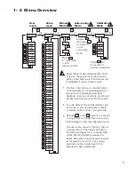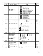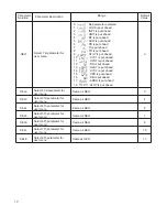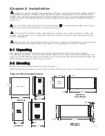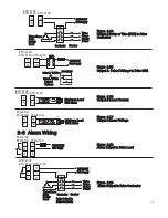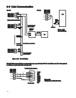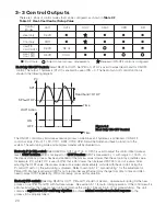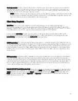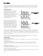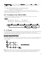
1- 5 Menu Overview
9
LOCK
INPT
UNIT
DP
INLO
SP1L
INHI
SP1H
SHIF
FILT
OUT1
O1TY
O1FT
O1HY
CYC1
PB
TI
TD
OFST
RAMP
RR
OUT2
O2TY
O2FT
O2HY
CYC2
CPB
DB
ALFN
ALMD
ALHY
ALFT
COMM
ADDR
BAUD
DATA
PARI
STOP
RELO
REHI
SEL1
SEL2
SEL3
SEL4
SEL5
SEL6
SEL7
SEL8
SP2
SP3
INPT
UNIT
PB
DP
TI
TD
CYC1
ADDR
PV, SV
H_ _ _
ADLO
ADHI
RTDL
CJLO
RTDH
CJHI
5 sec.
6.2 sec.
7.4 sec.
9.8 sec.
User
menu
Setup
menu
Manual
Mode
Calibration
Mode
*2
*1
Apply these modes will break the control
loop and change some of the previous
setting data. Make sure that if the system
is allowable to apply these modes.
The flow chart shows a complete listing
of all parameters. For actual application
the number of available parameters
depends on setup conditions, and should
be less than that shown in the flow chart.
You can select at most 8 parameters put
in the user menu by using SEL1~SEL8
contained at the bottom of setup menu.
Release , press again for 2 seconds
or longer (but not longer than 3 seconds),
then release to enter the calibration menu.
The user menu shown in the flow chart is
corresponding to the default setting for
the SEL parameters SEL1 to SEL8. SP3
will be hidden if NONE is selected for
ALFN. SP2 will be hidden if alarm function
is not selected for OUT2. The unused
parameter will be hidden even if it is
selected by SEL parameters.
*1:
*2:
Press for
5 seconds to
perform calibration.
8.6 sec.
C_ _ _
Release
then press
for 5 seconds
to start
auto-tuning
mode.
Press
for 5 seconds
to start
manual control.
Auto-tuning
Mode
*3:
*3

