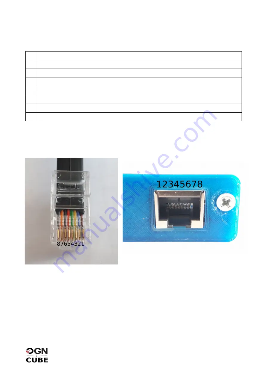
[Model A] RJ45 Connector Pinout
The meaning of the RJ45 pins (model A only) is as follows:
1
GND
2
GND
3
CUBE RX (TTL at VCC level!)
4
CUBE TX (TTL at VCC level!)
5
TX OFF
6
(not connected)
7
VCC (external power input 5-15V)
8
VCC (external power input 5-15V)
CAUTION!
Relying solely on the cable colours can be misleading as cables sourced from various
vendors can be marked differently. Hence it is better to consider the plug by its clip on one side.
Notes regarding the pins #3+4
:
voltage level of the TTL serial line is determined by the external
power input on pins #7+8. In case the power voltage is 5V you can connect your PDA with 5V TTL
I/O directly. For RS232 connection you need a level converter!
Notes regarding pin #5:
this input is designed to turn off radio transmission while maintaining the
reception on. To activate TX OFF you need to connect this pin using a two-way switch to ground
(GND). Otherwise keep it floating (do not connect anywhere).
OGN CUBE3 Installation and User’s Manual
Page 9 of 12
Illustration 4: RJ45 pin denotion with the
clip at the bottom side of the plug
Illustration 5: RJ45 pin denotion on the front face of the
unit with the clip at the bottom side


