background image

ORIGINAL INSTRUCTIONS
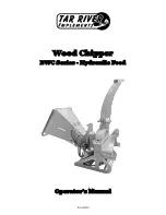
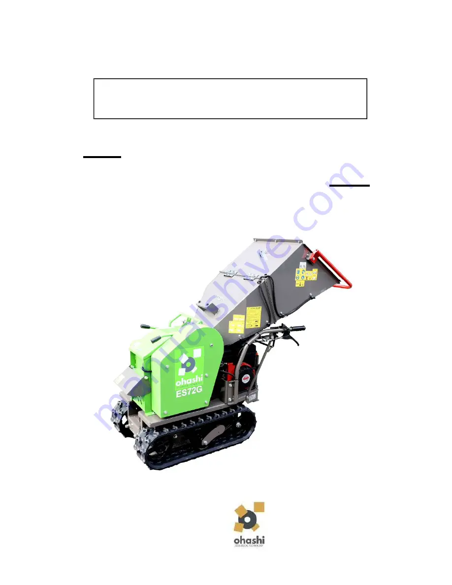
WOOD CHIPPER

ES72G

OHASHI INC.
401 Sakimura, Chiyoda, Kanzaki
Saga 842-0065, Japan
EUROPE TEL : +44 20 3286 2252
JAPAN TEL : +81 952 44 3135
WEB : www.ohashi-inc.com
E-mail : global@ohashi-inc.com

                   is separately provided by the engine manufacturer.

                   safety instructions, controls, servicing and maintenance of the 

OPERATION MANUAL

                   Before attempting to operate this machine, read and fully understand 
                   the contents of this Operation Manual. Make yourself familiar with 

                   machine. Operators must also read through the engine manual which 

Summary of Contents for ES72G

Page 1: ...i inc com E mail global ohashi inc com is separately provided by the engine manufacturer safety instructions controls servicing and maintenance of the OPERATION MANUAL Before attempting to operate thi...

Page 2: ...checks and servicing on a routine basis Take care of detecting even a small problem in the early stage before it becomes a big problem If you have some problem with the machine do not put the machine...

Page 3: ...ER CLOGGING RELEASE 22 REGULAR MAINTENANCE 23 KNIFE BASICS 23 PARKING BRAKE 28 REMOVE AFFIX KNIVES 24 ROTOR CLUTCH 29 KNIFE ADJUSTMENT 25 FEED ROLLER CHAIN 30 RE FUELING 26 RUBBER CRAWLER 31 TRANSPORT...

Page 4: ...before attempting to operate it while the engine is running or hot 2 If safety decals are torn and illegible obtain 4 Do not fill the fuel tank indoors new ones from our dealers and replace them 5 Wip...

Page 5: ...placed to their proper location as indicated below For locations of other decals see the following photographs and illustrations and affix them to their respective places Keep all decals always legibl...

Page 6: ...decals see the following photographs and illustrations and affix them to their respective places Keep all decals always legible Location of SAFETY decals INSTRUCTION DECAL SAFETY DECAL FEED BOX 9 CUTT...

Page 7: ...ove The details of Ohashi inc the CE mark and the specific details of the machine purchased Before starting the engine perform the following to maintain the machine in good condition As well as readin...

Page 8: ...m the operators control area Be careful not to damage the crawlers or the transmission by driving into holes or over obstacles Oil lubrication points Refer to Lubrication Chart in this user manual for...

Page 9: ...fore do not approach or put your hands or body near the feed box when the machine is operating The rotor clutch lever activates the rotor Pull the rotor clutch lever from OFF to ON slowly Ensure the t...

Page 10: ...slope or on a slope which is too steep or the machine may tip and crush you Load and unload the machine in the correct manner or injury may occur When loading or unloading the machine onto a truck tra...

Page 11: ...STOP area to stop the feed roller movement The brake handle activates the transmission and initiates the movement of the machine To initiate the movement of the machine hold down the brake handle To...

Page 12: ...ard books newspapers rubber glass or any other non wood material into the hopper to be chipped or damage will occur to the machine Moving parts may cut flesh and cause serious injury Feed material occ...

Page 13: ...CALS The shift lever allows the machine to move forward or in reverse To initiate the movement of the machine move the shift lever to FORWARD or REVERSE and hold down the brake handle 24 SHIFT LEVER 1...

Page 14: ...tch V belt Max diameter of wood treated mm 70 Cutting 2 chipper knives and a counter knife Infeed dimensions mm 180x90 Feeding system Electromagnetic clutch with automatic no stress system Discharge s...

Page 15: ...r Cover Left Side Cover Shift Lever Transmission Throttle Lever Idle Wheel Sprocket Wheel Right Side Cover Right Side Cover Engine Left Turning Control Lever Crawler Tracks Feed Roller Release Track R...

Page 16: ...nd stones metals rope glass wires and other such non organic man made materials are NOT contained in material to be inserted for chipping shredding 3 DO NOT operate machine s chipping shredding functi...

Page 17: ...and ensure machine has sufficient transmission oil and gasoline 3 9 CLEAN engine and track crawlers 10 CHECK for incorrect tension cracks and or wear of belts and chains 11 LUBRICATE with Shell Spirax...

Page 18: ...ine Switch to ON 2 Rotor clutch lever should be in the OFF position 7 Grasp recoil start cord to a compression position pull smoothly and with sufficient vigor 8 After the engine starts allow the engi...

Page 19: ...lever in Forward or Reverse 4 Close the fuel cock 3 Hold the brake handle down and adjust throttle When the brake handle is up the parking brake is engaged automatically When the brake handle is held...

Page 20: ...lever side clutch lever under the right handle Be careful of adjusting the throttle too quickly as any slopes or obstacles may unbalance the machine or cause it to tip over which may cause serious inj...

Page 21: ...t it in the correct position so that the rubber the wheel crawlers crawlers of the machine are positioned in the Serious accident may happen if the machine is center of the ramps not fixed firmly insi...

Page 22: ...ever in the middle c Pay attention to machine noise when the position between OFF and ON for 5 seconds machine is operated in a place where before fully moving it to the ON position people are living...

Page 23: ...dealer to repair the device immediately 1 After starting the engine putting the engine to full throttle and putting the rotor clutch to ON check that the feed switch is in the START position 5 Do not...

Page 24: ...nt the feed roller must not start yet 3 Switch the feed switch to the safety bar release After reading and understanding all the position and then return the feed switch to start to instructions in th...

Page 25: ...oved Be careful of the feed roller and feed box when clogged material is released from under the feed roller When clogged material is released the feed roller suddenly drops down and would crush a per...

Page 26: ...rds the centre is approx 13mm wide 4 REPLACE all covers guards and housing parts after inspection When sharpening do not sharpen so much that width of the strong steel strip becomes less than 5mm At t...

Page 27: ...er in open position 3 Open rotor cover to remove counter knife Alternate edges or replace knife with a new one Tightly secure the 2 fixing bolts 4 After mounting the counter knife the clearance betwee...

Page 28: ...tions at Remove Affix Knives 2 Insert 0 5mm gauge instrument between the each chipper knife and the counter knife as shown in the diagram below 3 Ensure the 0 5mm gauge can only just barely fit betwee...

Page 29: ...ng 1 Deteriorated engine oil decreases the machine s 2 Remove the Hopper Lock Pin and open the hopper operating ability and can cause engine failure Periodically change engine oil 3 Fold the hopper an...

Page 30: ...ide clutch wire adjusting nuts on each side of the metal brace until the turning handle responds as desired when engaged 3 Tighten the adjuster nuts securely The threaded part of the wire on the side...

Page 31: ...at the same time the brake drum d Replace the brake shoe Replace the seal gasket too if necessary Refit all parts tightly e Adjust the parking brake wire to achieve adaquate response from the brake ha...

Page 32: ...clutch arm d Move the engine in the direction away from into one of the 3 holes Must detach rotor arm first the rotor thus tightening the rotor clutch belt The gap between the outer edge of the engine...

Page 33: ...to the chains remove them before attaching the engine to the machine frame oiling e Remove the bolts M10 fixing the rotor belt holder Use machine oil SAE20 and remove the rotor belt holder and the ro...

Page 34: ...3 Loosen the crawler s lock nuts 4 Turn the crawler bolt and adjust so that the clearance between crawler and wheel illustration is about 10 15 mm wheels in parallel 5 Tighten the lock nuts securely...

Page 35: ...chine ability but also machine seating it fully into the hole failure Periodically drain old oil and pour required amount of new oil If the engine carburetor and governor are not working correctly the...

Page 36: ...that may lead to fuel leak immediately replace it Fuel leak can cause a fire Keep Fire Away 1 Remove the cover and the separate the Never perform any of these tasks with the outer foam cover from the...

Page 37: ...nd cleaning of air cleaner Inspection and tightning of bolt and nut at each place Check for fuel and oil leaks Change of engine oil Check and adjustment of valve clearance Removal of carbon in combust...

Page 38: ...ART Lubrication Points Gear oil Transmission Rotor bearing Rotor bearing Gasoline tank Gasoline Engine oil Sprocket refer to picture information Machine oil Lubricant SAE20 Lithium Grease inside the c...

Page 39: ...e operating the machine check if the parts are well fastened CAUTION Rotor Bearing Unit Fixed Bolts Feed Roller Arm Fixed Bolt Engine Fixed Bolts and Nuts 2 on each side 4 on the left side 2 on the ri...

Page 40: ...to clean the components near the engine oil reservoir or electronic components Use compressed air a brush or cloth to clean dirt dust and debris from these sections 1 Wash the machine after use on th...

Page 41: ...lubricating oil circulate in the engine 7 Clean each components of the machine with oil cloth Cover the machine to protect it and keep it clean Store the machine in a clean dry storage area Check if...

Page 42: ...Rotor bearing unit left UC205 A7040205000 500 hrs Estimated life varies on usage Feed roller bearing unit SBPFL204 A7055204000 1000 hrs Sprocket bearing 68032ZZ A70680302ZZ 200 hrs Feed roller chain 3...

Page 43: ...ter and carburetor Fill new fuel In particular check for clogged main jet of the carburetor and clean it thoroughly Replace the re adjusted or new plug and insert the plug cap securely Clogging 5 Poor...

Page 44: ...e 7 5A Replace it Defective 1 Electric wiring FEED ROLLER CHECK Check points 1 Engine power 2 Feed switch Replace it Defective 3 Feed roller Remove the clogged material Clogging 4 Feed roller chain Re...

Page 45: ...hine safety covers guards and housing are closed and fitted securely Test Safety Bar is working properly Check rubber crawler tension Adjust first 10 20 hrs Sharpen the chipper knives Check and cleani...

Page 46: ...should also wear ear protection to protect from ear damage The Guaranteed Sound Power Level for this machine was recorded at 108dB Lwa The Sound Pressure Level for this machine was recorded at 80 3dB...

Page 47: ...MACHINE DIMENSIONS 44...

Page 48: ...AM Toggle switch Relay Relay E G regulator E G regulator E G M Electro magnetic clutch Condenser Heat shrinkable tube Soldered Soldered Micro switch Blue Black Hopper switch NO Safety bar switch NC Ro...

Page 49: ...Directive 2011 65 EU on the Restriction of the use of certain Hazardous Substances in electrical and electronic equipment 2011 65 EU Applied Harmonized Standards EN 13525 2005 Forestry machinery Wood...

Page 50: ...following The entire machine as a whole Faults which arise due to actions inactions that are not part of the correct and appropriate handling of the machine guidance given by Ohashi Any faults or dam...

Page 51: ...le fighting the fire If engine takes fire or emits smoke from other sections than exhaust outlet stop the machine immediately switch Engine Switch to OFF position Extinguish the fire Pay extra caution...

Page 52: ......

Page 53: ......

Page 54: ...Ohashi Inc 401 Sakimura Chiyoda Kanzaki Saga 842 0065 Japan EUROPE TEL 44 20 3286 2252 JAPAN TEL 81 952 44 3135 E MAIL global ohashi inc com www ohashi inc com...

Reviews: