ADVENTURER BALANCES
EN-51
9.4.2
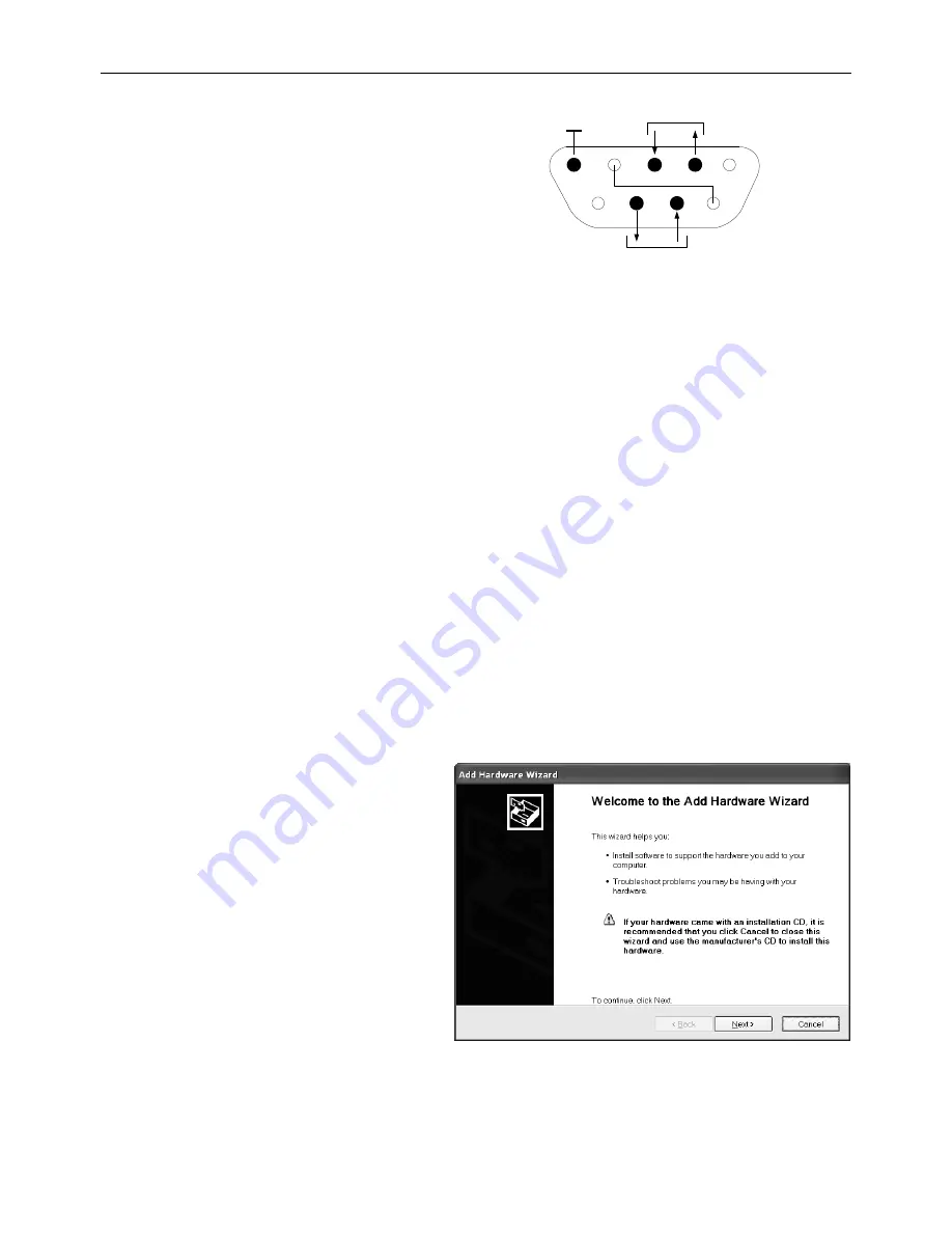
RS232 (DB9) Pin Connections
Pin 2: Balance transmit line (TxD)
Pin 3: Balance receive line (RxD)
Pin 5: Ground signal (GND)
Pin 7: Clear to send (hardware handshake) (CTS)
Pin 8: Request to send (hardware handshake) (RTS)
9.5
The USB Interface
The Ohaus USB Interface is a unique solution to the problem of connecting a balance to a computer using a
Universal Serial Bus (USB). USB devices are categorized into classes such as disk drives, digital cameras,
printers, etc. Balances do not have a commonly used class so the Ohaus USB interface uses a generic interface
based on the RS232 serial standard.
Data sent from the balance to a computer is in USB format. The USB data is directed to a
virtual port
.
This port
then appears as an RS232 port to the application program.
When sending a command from a computer to the balance, the application program sends a command to the
virtual port
as if it were an RS232 port. The computer then directs the command from the
virtual port
to the
computers USB connector where the balance is connected. The port receives the USB signal and reacts to the
command.
The USB Interface includes a CD with the software drivers to create the required
virtual port
on the computer.
System Requirements
PC running Windows 98
®
, Windows 98SE
®
, Windows ME
®
, Windows 2000
®
, Windows XP
®
, Windows 7
®
or
Windows 8
®
(32-bit).
Available USB port (Type A, 4-pin, female)
USB Connection
The balance’s USB port terminates with a 4-pin, female, USB Type B connector.
A USB Cable (type B/male to type A/male) is required (not supplied).
1. Ensure that the balance is powered on and working properly.
2. Power on the computer and verify that its USB port is enabled and working properly.
3.
Plug the cable’s USB connectors into the computer’s USB port and the balance’s USB port. Windows®
should detect a USB device and the New Hardware Wizard will be initialized.
Virtual Port Software Installation
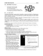
1.
Insert the supplied CD into the computer’s CD
drive.
Different versions of Windows
®
have slightly
different steps to load the driver that is on the
CD. In all versions the New Hardware Wizard
guides you through the required steps to select
the driver that is located on the CD.
2. After clicking Finish, the virtual port should be
ready for use.
Windows
®
typically adds the virtual port in
sequence after the highest number COM port.
For example, on P
C’s equipped with up to 4
COM ports, the virtual port will be COM5.
When using the USB interface with programs
that limit the number of COM port designations
(e.g. Ohaus MassTracker allows only COM1, 2,
3, & 4), it may be necessary to assign one of
these port numbers to the new virtual port.
Example of Windows XP Hardware Wizard
This can be done in the Port Settings of the Device Manager utility, found in the Windows Control Panel.
1
5
6
9
Data
GND
Handshake
Female


