Defender 2200 Bench Scale
EN-8
2. INSTALLATION
2.1 Unpacking
Unpack and inspect the product to make sure that all components have been included.
The package includes the following:
•
2200 Series Indicator
•
Column Assembly
•
AC Adapter
•
Mounting Bracket
•
Knobs (2)
•
Base and Weighing Pan
•
Warranty Card
•
Instruction Manual
• LFT
Sealing Kit
2.2 External
Connections
2.2.1 RS232 interface Cable to the indicator
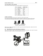
Connect the optional RS232 cable to the RS232 connector Figure 2-1).
Pin Connection
1 N/C
2 TXD
3 RXD
4 N/C
5 GND
6 N/C
7 N/C
8 N/C
9 N/C
1
2
3
4
5
6
7
8
9
Figure 2-1. RS232 Pins.
2.2.2 AC Power
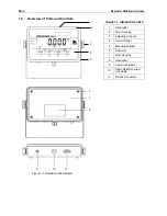
Connect the AC Adapter to the power receptacle (Figure 1-1, item 9), then plug the AC Adapter into an electrical
outlet.
2.2.3 Mounting Bracket to the Indicator
Align the mounting bracket over the threaded holes in the side of the indicator and install the knobs.
Adjust the indicator to the desired angle and tighten the knobs.
2.3 Internal
Connections
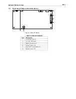
Some connections require the housing to be opened.
2.3.1 Opening the Housing
CAUTION: ELECTRICAL SHOCK HAZARD. REMOVE ALL POWER CONNECTIONS TO THE
INDICATOR BEFORE SERVICING OR MAKING INTERNAL CONNECTIONS. THE HOUSING
SHOULD ONLY BE OPENED BY AUTHORIZED AND QUALIFIED PERSONNEL, SUCH AS AN
ELECTRICAL TECHNICIAN.
Remove the four Phillips head screws from the rear housing.
Open the housing being careful not to disturb the internal connections.
Once all connections are made, reattach the front housing.

