Defender 2200 Bench Scale
EN-9
2.3.2 Scale Base to the indicator
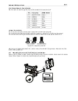
Pass the load cell cable through the strain relief and attach it to terminal block J7.
Pin Connection
WIRE COLOR
J7-1 +EXCITATION Green
J7-2 +SENSE
Black
J7-3 +SIGNAL
Red
J7-4 GROUND
White
J7-5 –SIGNAL
Blue
J7-6 –SENSE
Brown
J7-7 –EXCITATION Yellow
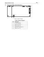
Jumper Connections
For a 4-wire load cell with no sense wires: Jumpers W1 and W2 must be shorted.
For a 6-wire load cell that includes sense wires, see Figure 2-2. Jumpers W1 and W2 must be opened.
For load cells with an extra ground shield wire: Connect the shield to the center position (GND) of J7.
Figure 2-2. Jumper Connections.
After wiring is completed and jumpers are in place, replace the indicator housing screws. Make sure the strain
relief is properly tightened.
2.4
Mounting the Column to the Base and Indicator
Fasten bottom of bracket to base, thread Load Cell cable through column to indicator, fasten column to indicator
bracket. Mount bracket to indicator and install knobs as shown below.
10mm

