Defender 5000 Indicators
EN-67
11. APPENDICES
11.1 Appendix A
MT Standard Continuous Output
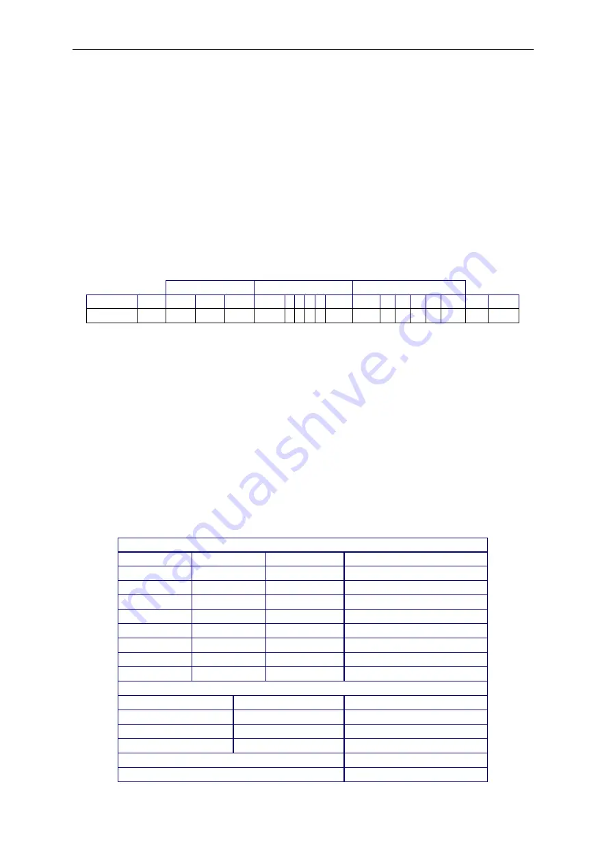
A checksum character can be enabled or disabled with continuous output. The data consists of 17 or
18 bytes as shown in the standard continuous output.
Table 5-1.
Non-significant weight data and tare data digits are transmitted as spaces. The continuous output
mode provides compatibility with OHAUS products that require real-time weight data. the standard
continuous output.
Table 5-1 shows the format for the standard continuous output.
Table 5-1: Standard Continuous Output Format
Status
2
Indicated Weight
3
Tare Weight
4
Character 1
2
3
4
5
6 7 8 9 10
11
12 13 14 15 16
17 18
Data
STX
1
SB-A SB-B SB-C MSD - - - - LSD MSD - - - - LSD CR
5
CHK
6
Continuous Output Format Notes:
1.
ASCII Start of Text character (02 hex), always transmitted.
2.
Status bytes A, B and C. Refer to Table 5-2, Table 5-3, and Table 5-4 for details of the
structure.
3.
Displayed weight. Either gross or net weight. Six digits, no decimal point or sign.
Insignificant leading zeroes are replaced with spaces.
4.
Tare weight. Six digits of tare weight data. No decimal point in field.
5.
ASCII Carriage Return <CR> character (0D hex).
6.
Checksum, transmitted only if enabled in setup. Checksum is used to detect errors in the
transmission of data. Checksum is defined as the
2’s complement of the seven low order
bits of the binary sum of all characters preceding the checksum character, including the
<STX> and <CR> characters.
Table 5-2, Table 5-3, and Table 5-4 detail the status bytes for standard continuous output.
Table 5-2: Status Byte A Bit Definitions
Bits 2, 1, and 0
2
1
0
Decimal Point Location
0
0
0
XXXXX00
0
0
1
XXXXX0
0
1
0
XXXXXX
0
1
1
XXXXX.X
1
0
0
XXXX.XX
1
0
1
XXX.XXX
1
1
0
XX.XXXX
1
1
1
X.XXXXX
Bits 4 and 3
4
3
Build Code
0
1
X1
1
0
X2
1
1
X5
Bit 5
Always = 1
Bit 6
Always = 0


