CHAPTER 2 DIAGNOSTIC GUIDE
2.1 TROUBLESHOOTING
This section of the manual provides guidelines for evaluating the condition and performance of a
Base scale, and a standard troubleshooting methodology to follow.
2.1.1 Checking Load Cells for Trouble
1.
Visual Check:
Examine the Load Cell for signs of bending, twisting or corrosion.
– Remove any shipping materials from between the upper and lower Housings, if
present.
– Clean the unit before evaluating any mechanical problems. In some cases,
debris may have accumulated inside the Base Housing. Make sure there is no
buildup of any foreign material.
– Examine the Base Housing for dents, bent Platform or signs of physical abuse
that could cause the Base to malfunction. Make sure that the proper Platform is
supplied with the Base. Replace all damaged parts. See Chapter 5 for parts list.
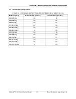
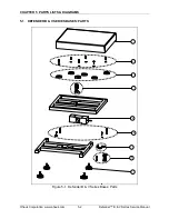
– Remove the Platform from the Base. Check that the Overload Stops are not
touching the Top Plate. (See Figure 5-1, Chapter 5.) This would restrict
movement, causing improper operation of the Base. If the Overload Stops are
improperly set, adjust them. (See Section 3.3.)
– Check the metal surfaces of the Platform. All surfaces should be parallel.
If the platform is deformed, it should be replaced.
– Check the cables leading to the Load Cell for cuts, abrasions or other signs of
excessive wear and tear.
– Check for a bent or twisted Load Cell:
Place the top surface and then each of
the sides of the Load Cell on a flat surface, to see if it rests flat and even. A gap
indicates a bent or twisted Load Cell.
– Examine the Load Cell for corrosion due to high humidity or exposure to
chemicals.
– A Load Cell that is even slightly bent or corroded should be replaced.
2.
Perform a Resistance Test
, to determine if the Load Cell is severely damaged or a
short circuit to the frame has occurred. (See Chapter 4 for details.)
3.
Perform an Output Voltage Test
:
Measure the no load, 50% load and full load
output.
The reading should meet the Load Cell specifications. (See Chapter 4.)
–
The Load Cell output should be very close to linear over its capacity range.
Defender™ B & V Series Service Manual
2-1
Ohaus Corporation www.ohaus.com
Summary of Contents for Defender D150BL
Page 2: ......
Page 4: ......
Page 12: ...CHAPTER 1 INTRODUCTION Ohaus Corporation www ohaus com 1 6 Defender B V Series Service Manual ...
Page 24: ...CHAPTER 4 TESTING Ohaus Corporation www ohaus com 4 6 Defender B V Series Service Manual ...
Page 30: ...APPENDIX A GLOSSARY Ohaus Corporation www ohaus com A 2 Defender B V Series Service Manual ...
Page 31: ......
Page 32: ... 80252594 P N 80252594 A SERVICE MANUAL DEFENDER B V SERIES BASES ...


