CHAPTER 4 TESTING
4.4 Consistency
Check
To check the system prior to installation, make the following measurements. (Also make these
checks if the Load Cell will not calibrate, or if the Indicator does not read correctly, or is giving
unstable readings.)
1. Using a voltmeter, measure and record the excitation voltage supplied by the Indicator.
Most Ohaus indicators supply 5 volts dc for the excitation voltage.
2. Using an mV meter, measure and record the signal voltage with no load on the base.
CAUTION:
IN THE NEXT STEP, DO NOT OVERLOAD THE BASE BEYOND FULL
CAPACITY RATING.
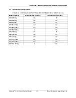
3. Using an mV meter, measure and record the signal voltage at the loads shown in
Table 4-2.
4. Compare the measured output readings with the theoretical values from the Load Cell
data. (See Table 4-2.)
TABLE 4-2. LOAD CELL OUTPUT READINGS (in mV with 5V Excitation)
Model/Capacity
Zero Load
50% Load
100% Load
D30BR/30kg
1.3 ± 1.0
Zero + 2.8
Zero + 5.6
D60BR/60kg
1.1 ± 1.0
Zero + 2.55
Zero + 5.1
D60BL/60kg
1.1 ± 1.0
Zero + 2.55
Zero + 5.1
D150BL/150kg
1.3 ± 2.0
Zero + 2.7
Zero + 5.4
D150BX/150kg
1.3 ± 2.0
Zero + 2.7
Zero + 5.4
D300BX/300kg
0.24 ± 2.0
Zero + 3
Zero + 6
D30VR/30kg
1.3 ± 1.0
Zero + 2.8
Zero + 5.6
D60VR/60kg
1.1 ± 1.0
Zero + 2.55
Zero + 5.1
D60VL/60kg
1.1 ± 1.0
Zero + 2.55
Zero + 5.1
D150VL/150kg
1.3 ± 2.0
Zero + 2.7
Zero + 5.4
D150VX/150kg
1.3 ± 2.0
Zero + 2.7
Zero + 5.4
D300VX /300kg
0.24 ± 2.0
Zero + 3
Zero + 6
Ohaus Corporation www.ohaus.com
4-2
Defender™ B & V Series Service Manual
Summary of Contents for Defender D150BL
Page 2: ......
Page 4: ......
Page 12: ...CHAPTER 1 INTRODUCTION Ohaus Corporation www ohaus com 1 6 Defender B V Series Service Manual ...
Page 24: ...CHAPTER 4 TESTING Ohaus Corporation www ohaus com 4 6 Defender B V Series Service Manual ...
Page 30: ...APPENDIX A GLOSSARY Ohaus Corporation www ohaus com A 2 Defender B V Series Service Manual ...
Page 31: ......
Page 32: ... 80252594 P N 80252594 A SERVICE MANUAL DEFENDER B V SERIES BASES ...


