CHAPTER 1 INTRODUCTION
1.8 HOW LOAD CELLS OPERATE
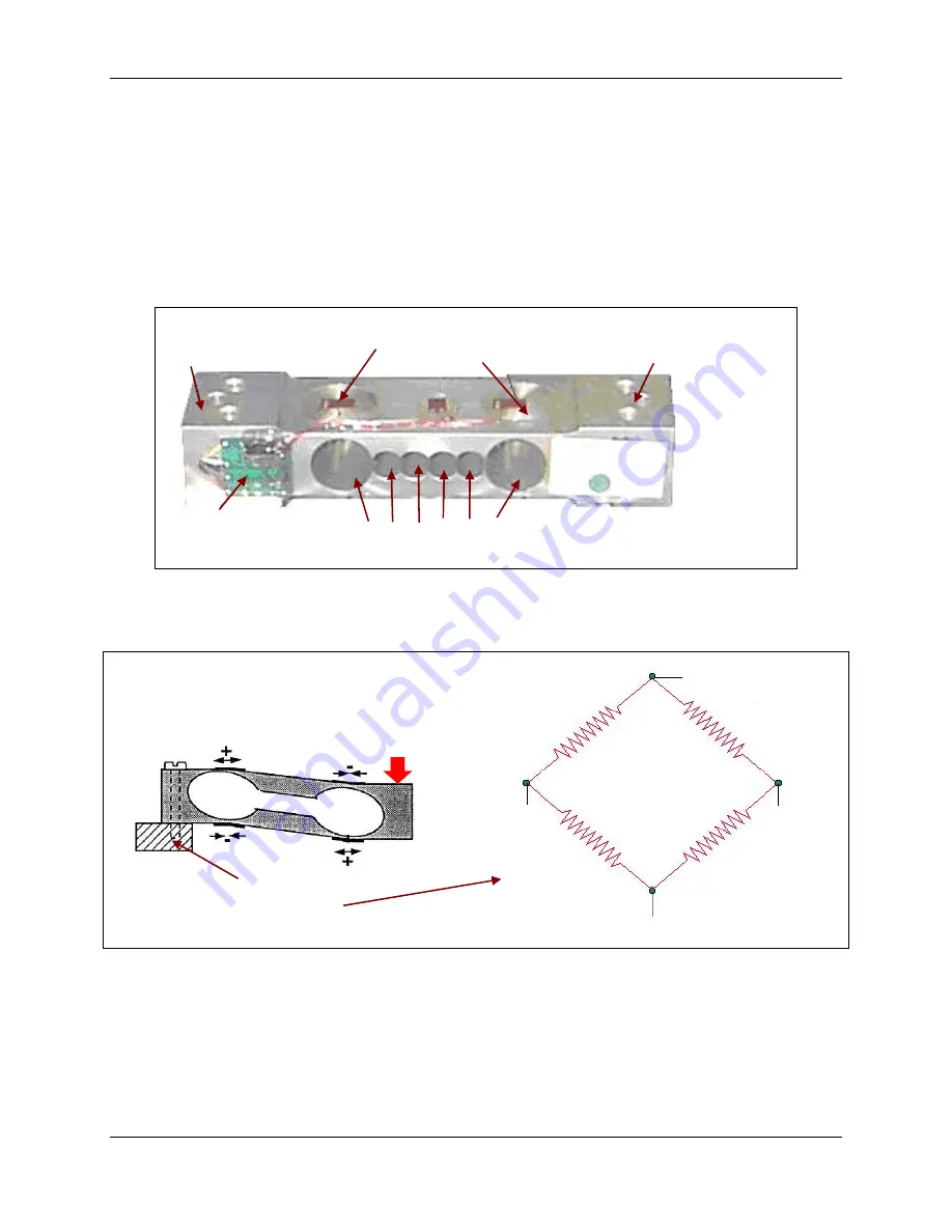
Load Cells are devices that convert force into a signal. Defender Bases have a Strain Gauge
Load Cell, which is made from a metal beam with holes drilled in it. Strain gauges are affixed to
the beam at the top and bottom to measure changes in the beam due to deflection. The gauges
are bonded very securely to the metal, where they sense very small deflections in the metal
caused by the load being applied to the cell. Because the signal levels are very small, the
circuit is protected from all outside influences such as moisture, physical damage, or electrical
interference.
Attachment points to
Platform
Strain Gauges
Beam
Printed Circuit Board
completing Wheatstone
Bridge circuit
Holes drilled in Strain
Gauge Load Cell
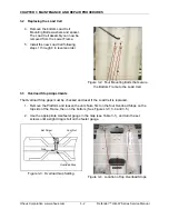
Figure 1-1. Strain Gauge Load Cell.
The strain gauges are wired into a Wheatstone Bridge Circuit. (See Figure 1-2.)
Force
Wheatstone Bridge Circuit
Strain Gauge
+
+
Strain Gauge
–
Strain Gauge
Strain Gauge
–
Printed Circuit Board (PCB )
completing Wheatstone
Bridge circuit
Figure 1-2. Downward force on the Platform bends the beam, causing two gauges to stretch
and two to compress in opposition, changing the electrical resistance of the circuit.
At zero load, all strain gauges are unstressed. Weight placed on the Platform bends the
beam, causing two gauges to stretch and two to compress in opposition, changing the
electrical resistance of the circuit.
Ohaus Corporation www.ohaus.com
1-6
Defender™ H-Q-W Series Service Manual
Summary of Contents for Defender D15HR
Page 2: ......
Page 4: ......
Page 34: ...APPENDIX A GLOSSARY Ohaus Corporation www ohaus com A 2 Defender H Q W Series Service Manual...
Page 35: ......
Page 36: ...80252596 P N 80252596 SERVICE MANUAL DEFENDER H Q W SERIES BASES...


