CHAPTER 4 TESTING
4.3 Calibration with an External Indicator
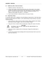
1. Install the Load Cell. (See Section 3.2.)
2. Connect the excitation, signal shield and sensing wires (if provided), to the Indicator.
Calibrate the Indicator to read the load in the units required, for example, kilograms or
grams. (Consult the Indicator instruction manual for calibration procedures.) For
calibration mass weights, see Table 1-1, in Chapter 1.
3. Check that the Indicator is reading correctly over a range of values.
4.4 Consistency
Check
To check the system prior to installation, make the following measurements. (Also make these
checks if the Load Cell will not calibrate, or if the Indicator does not read correctly, or is giving
unstable readings.)
1. Using a voltmeter, measure and record the excitation voltage supplied by the Indicator.
Most Ohaus indicators supply 5 volts dc for the excitation voltage.
2. Using an mV meter, measure and record the signal voltage with no load on the base.
CAUTION:
IN THE NEXT STEP, DO NOT OVERLOAD THE BASE BEYOND FULL
CAPACITY RATING.
3. Using an mV meter, measure and record the signal voltage at the loads shown in
Table 4-2.
4. Compare the measured output readings with the theoretical values from the Load Cell
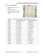
data. (See Table 4-2.)
Ohaus Corporation www.ohaus.com
4-2
Defender™ H-Q-W Series Service Manual
Summary of Contents for Defender D15HR
Page 2: ......
Page 4: ......
Page 34: ...APPENDIX A GLOSSARY Ohaus Corporation www ohaus com A 2 Defender H Q W Series Service Manual...
Page 35: ......
Page 36: ...80252596 P N 80252596 SERVICE MANUAL DEFENDER H Q W SERIES BASES...

