3-3
CHAPTER 3 SCALE TESTING AND CALIBRATION
3.3.2 Excitation and Output Voltage Test (Cont.)
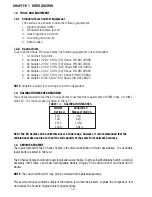
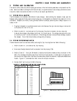
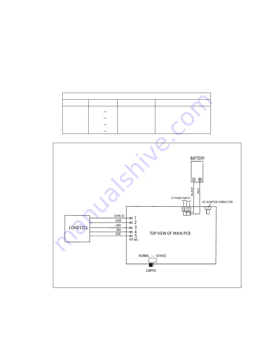
4. Refer to Figure 3-2 and measure the voltages on points 3 and 4, +SIG and –SIG points. These
measurements represent the output of the Load Cell. Repeat measurements at 50% and full scale
capacities. See Table 3-3 for typical readings.
NOTE
: Table 3-3 indicates typical readings, actual values can vary, but should remain linear
throughout the entire range.
If readings are out of tolerance, replace the Load cell. See Section 4.4 or 4.5 for Load Cell
replacement.
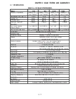
TABLE 3-3. LOAD CELL OUTPUT READINGS.
NOMINAL OUTPUT IN MILLIVOLTS AT 5 VOLTS EXCITATION
CAPACITY
NO LOAD
50%
100%
3 kg
2.7 +1.5 no load + 3.2
no load + 6.4
6 kg
1.9 +1.5 no load + 4.4
no load + 8.8
15 kg
1.2 +1.5 no load + 5.2
no load + 10.3
30kg
0.5 +1.5 no load + 4.9
no load + 10.4
Figure 3-2. EC Series Scales Interconnection Diagram.
Summary of Contents for EC Series
Page 2: ......
Page 4: ......
Page 14: ...2 6 CHAPTER 2 DIAGNOSIS...
Page 30: ...3 16 CHAPTER 3 SCALE TESTING AND CALIBRATION...
Page 52: ...A 4 APPENDIX A SERVICE MODES...
Page 55: ......
Page 56: ...PN 80010584 B SERVICE MANUAL EC SERIES SCALES 80010584...


