4-1
CHAPTER 4 REPAIR PROCEDURES
4.
REPAIR PROCEDURES
This section describes how to change individual components of the EC Series Scales. When doing this,
please refer to the drawings and parts lists in Section 5.
Important: After replacing components, an operational test of the scale must always be carried out, (see
Section 3.6).
4.1
REMOVING TOP HOUSING
To gain access to the components in the scale, perform the following procedures.
1. Remove power from the scale by disconnecting the AC adapter. Make sure the scale is off.
2. Carefully lift and remove the Pan and Pan Support from the scale.
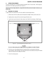
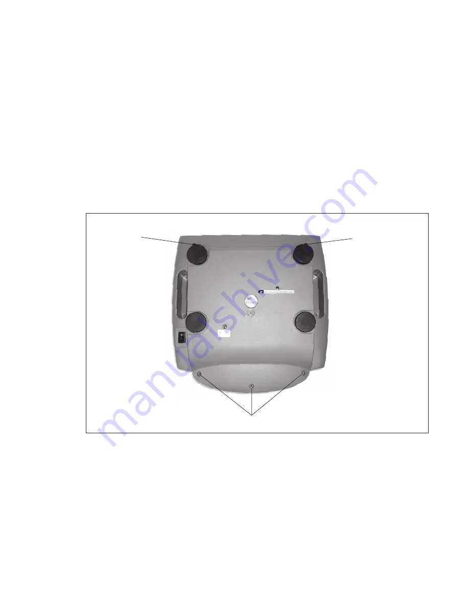
3. Turn the scale over and remove the five screws, which hold the Top Housing. Refer to Figure
4-1.
Figure 4-1. Top Housing Retaining Screws Location.
CAUTION
Use care in the next step as the Display PCB wiring is attached to the Main PC board.
4. Place the scale in the upright position and carefully lift the Top Housing from the Base
and tilt forward. Reach under the Top Housing from the front and carefully disconnect the flexible
cable from connector on the Display PC board.
5. Set the Top Housing aside.
RETAINING SCREWS
RETAINING SCREW
RETAINING SCREW
Summary of Contents for EC Series
Page 2: ......
Page 4: ......
Page 14: ...2 6 CHAPTER 2 DIAGNOSIS...
Page 30: ...3 16 CHAPTER 3 SCALE TESTING AND CALIBRATION...
Page 52: ...A 4 APPENDIX A SERVICE MODES...
Page 55: ......
Page 56: ...PN 80010584 B SERVICE MANUAL EC SERIES SCALES 80010584...


