4-8
CHAPTER 4 REPAIR PROCEDURES
4.3.2 Display PC Board Replacement (Cont.)
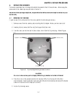
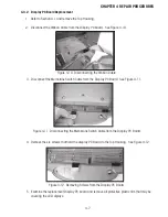
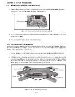
6. Install the replacement Display PC board with the six screws previously removed.
7. Connect the Membrane Switch Cable from the Top Housing to the Display PC Board and the Ribbon
Cable from the Main PC Board to the Display PC Board.
8. Reassemble and test the scale according to Performance Tests in section 3.6.
4.3.3 LCD Replacement
This procedure is performed when an LCD shows signs of visible damage such as a cracked glass or partial
display and the scale operates normally in all other functions.
NOTE
: This procedure is very difficult and should not be attempted unless you have the proper tools.
1. Perform steps 1 through 4 of Section 4.3.2.
2. Carefully unsolder all contacts of the defective LCD and remove the LCD. All solder holes on the
Display PC board must clean and open to accept the pins of the LCD.
3. Solder all connections, check the Display PC Board and make sure that solder has not spilled over
to other connections. Remove any protective film from the LCD and replace the LCD.
4. Continue with steps 6 through 8 of Section 4.3.2.
Summary of Contents for EC Series
Page 2: ......
Page 4: ......
Page 14: ...2 6 CHAPTER 2 DIAGNOSIS...
Page 30: ...3 16 CHAPTER 3 SCALE TESTING AND CALIBRATION...
Page 52: ...A 4 APPENDIX A SERVICE MODES...
Page 55: ......
Page 56: ...PN 80010584 B SERVICE MANUAL EC SERIES SCALES 80010584...


