3-12
CHAPTER 3 REPAIR PROCEDURES
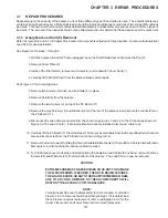
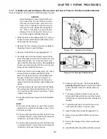
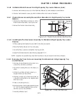
1.Place Force Coil Lever assembly in the des-
ignated position; check whether the alumi-
num sleeves are correctly positioned. See
Figure 3-16.
2.Turn back vertical adjustment screw (3) to
the original position. (See Figure 3-16).
3.Insert centring pins in the holes provided.
4.Insert the Force Coil Lever assembly fas-
tener screws and carefully tighten in the di
rection shown by the arrow (2.5 Nm) secur-
ing the NUTS to prevent movement. Ensure
that the Force Coil Lever remains in the
middle at the front.
CAUTION:
Load lever only in the direction shown by the
arrow to ensure the flexible bearings are not
compressed!
5.Attach Load Cell Board Temperature
Sensor Board and Position Sensor Assem-
bly and tighten screws.
6.Hold contact board to ensure the fine coil
wires can not tear off. Then, as described in
paragraph 3.1.16, remove the screw (2) from
the lever and screw to holder. (See Figure 3-14).
7.Take out centering pins.
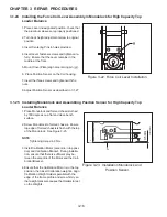
8.Screw Monoblock to formed chassis. Ensure
top edge of formed chassis is flush with the
top of the Monovblock. See Figure 3-17.
9.Mount overload protection on the Monoblock.
107
2
1
3.1.17
Installing the Force Coil Lever Assembly in Monoblock for Precision Top Loader
Balance
109
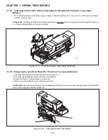
Figure 3-16. Force Coil Lever Installation.
Figure 3-17. Monoblock Mounting.
3
Summary of Contents for EXPLORER
Page 2: ......
Page 4: ......
Page 62: ...4 10 CHAPTER 4 TESTING ...
Page 88: ...5 26 CHAPTER 5 DRAWINGS AND PARTS LISTS ...
Page 106: ...APPENDIX B EXPLORER PRO EP LOADER B 10 ...
Page 112: ...APPENDIX D REPLACING BOTTOM DISPLAY BOARD D 4 ...
Page 113: ......
Page 114: ...PN 80250985 SERVICE MANUAL EXPLORER EXPLORER PRO AND VOYAGER BALANCES 80250985 ...

