CHAPTER 3 MAINTENANCE PROCEDURES
Ranger
™
(Count) 3000 Series Service Manual
3-5
Ohaus Corporation www.ohaus.com
TABLE 3-1. MOUNTING BOLT TORQUE SETTINGS
MODEL
TORQUE SETTING
R31P(E)1502
RC31P1502
6N to 8N
R31P(E)3
RC31P3
6N to 8N
R31P(E)6
RC31P6
6N to 8N
R31P(E)15
RC31P15
6N to 8N
R31P(E)30
RC31P30
6N to 8N
6. Set Overload Stops as shown in Section 3.6.
3.6 Setting the Overload Stops
The Overload Stop gaps must be checked and reset if the Load Cell is replaced. This
procedure requires test masses equal to the scale
’s capacity. (
See Table 3-2.)
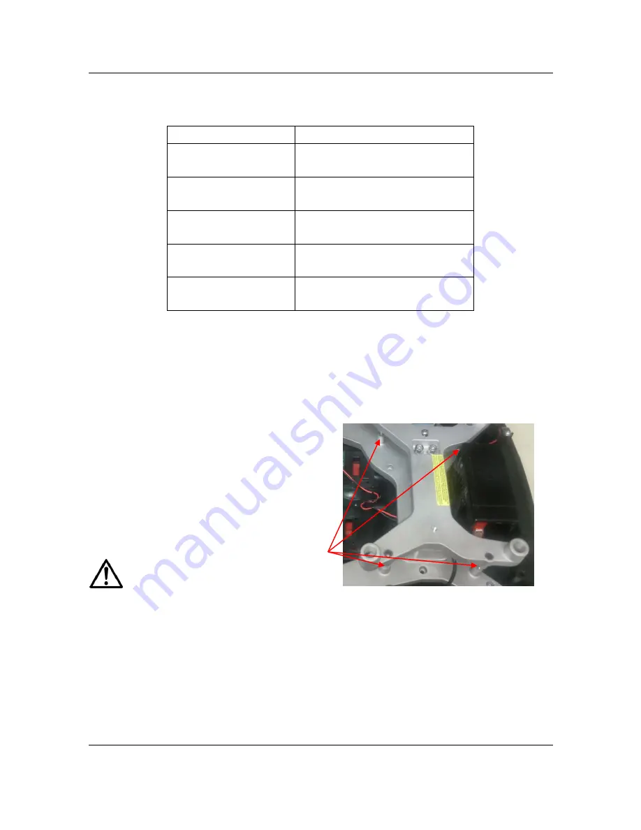
There are four Overload Stop Bolts. (See Figure 3-5.)
Adjust the Overload Stops, per Table 3-2:
1. Adjust the Overload Stop Bolt so that
the gap between the Load Cell Frame
and the Overload Stop Nut is equal to
the specification in Table 3-2. (The
gap can be tested by applying 100%
load, one corner at a time, at each
corner stop. If the gap is right, the
Load Cell Frame will just touch the
Overload Stop Nut.)
Note:
Be careful not to overload the
Load Cell, which would damage it.
2. Repeat this for all four corners.
3. Test the scale to see if full capacity
can be achieved.
Figure 3-5. Overload Stops.
Overload
Stops


