01/09/2006
Page - 28 -
8.1
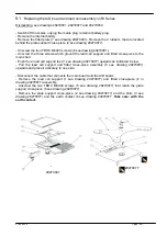
Replacing the A/D board and load cell assembly on RI Series
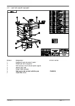
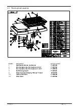
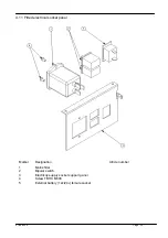
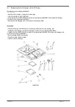
Dismantling: see drawings 29270001, 29270077 and 29270054.
- Switch off the scales, unplug the mains plug / external battery plug.
- Remove the internal battery.
- Remove the fitted plate (7 see drawing 29270001)- Remove the 2 rubbers that are located
behind the plate support cross-piece (2 see drawing 29270077).
- Unscrew the four TBHC M4X20 screws (6 see drawing:29270001).
- Unscrew the three screws which ground the load cell support and fitted cross-piece to the
main shell.
- Push the 2 load cell support feet (1 see drawing 29270077) upwards as indicated below.
- Pull the load cell support and fitted cross-piece assembly (5 see drawing 29270001)
upwards and place it delicately to one side.
- Disconnect the cable that connects the main board and the A/D board.
- Remove the load cell support (1 see drawing 29270077) and fitted cross-piece (2 in
drawing 29270077) assembly.
- Unscrew the two TBHC M6X40 screws (5 see drawing 29270077) that retain the plate
support cross-piece (5 see drawing 29270077).
- Remove the plate support cross-piece (2 see drawing 29270077) and the shim (3 see
drawing 29270077) and the earth contact (6 see drawing 29270077.
Take care: with the
earth contact.
29270001
29270077
Summary of Contents for RI Series
Page 1: ...RI Series Maintenance manual Range 15 kg d 5g Range 6 kg d 2g...
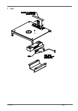
Page 21: ...01 09 2006 Page 21 5 Seal...
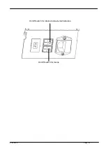
Page 40: ...01 09 2006 Page 40 On Off switch for internal and external batteries On Off switch for mains...
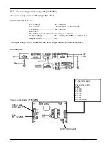
Page 44: ...01 09 2006 Page 44 10 3 2 Electrical diagram 29120154...
Page 50: ...01 09 2006 Page 50 10 4 7 Diagrams Main Board 71207283 1 6...
Page 51: ...01 09 2006 Page 51 Main Board 71207283 2 6...
Page 52: ...01 09 2006 Page 52 Main Board 71207283 3 6...
Page 53: ...01 09 2006 Page 53 Main Board 71207283 4 6...
Page 54: ...01 09 2006 Page 54 Main Board 71207283 5 6...
Page 55: ...01 09 2006 Page 55 Main Board 71207283 6 6...
Page 74: ...01 09 2006 Page 74...


