2-2
CHAPTER 2 THEORY OF OPERATION
2.2 TRANSDUCER OPERATION.
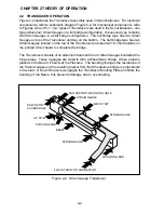
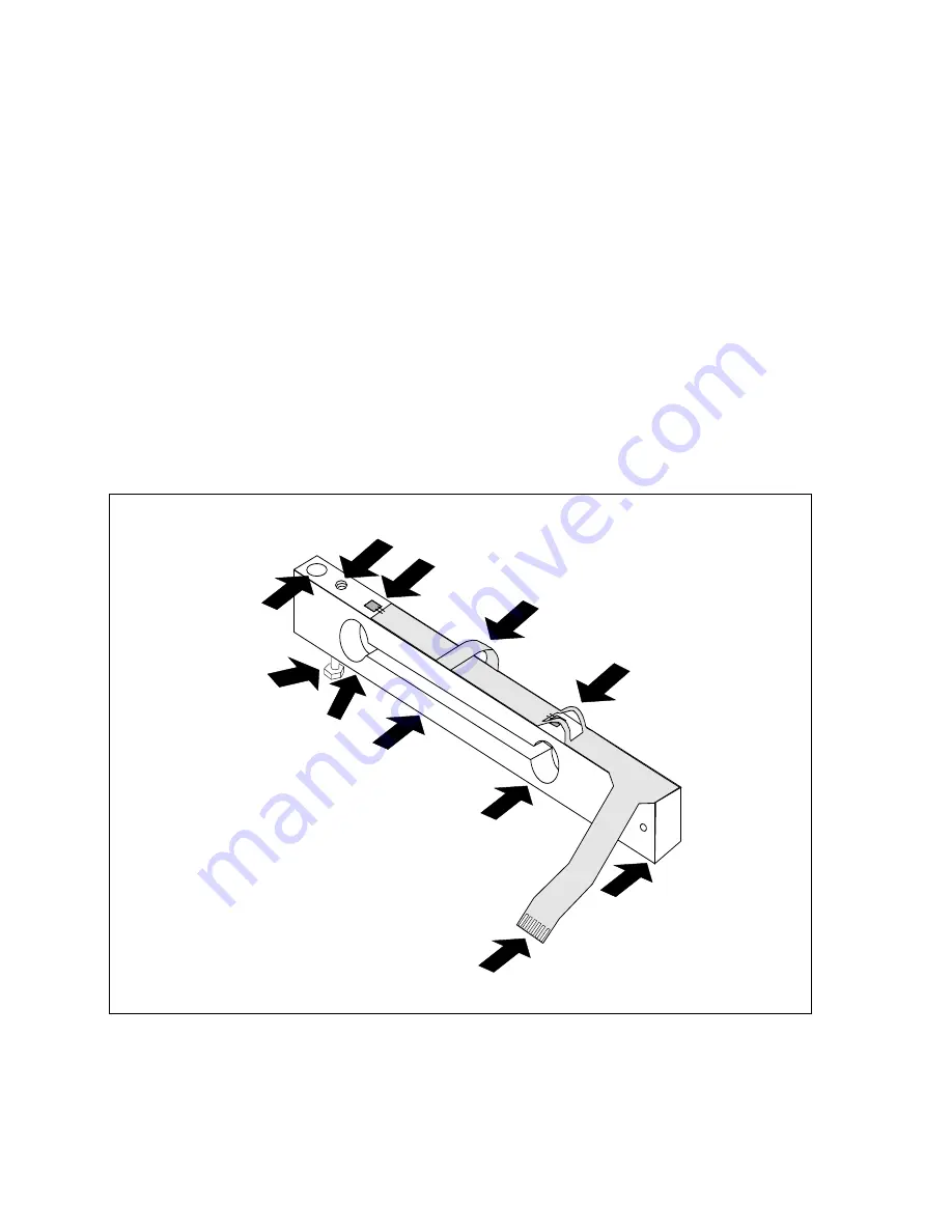
Figure 2-2 illustrates the Transducer assembly used in Scout balances. For electrical
components, refer to schematic diagram Figure 5-2, for mechanical components, refer
to Figures 2-2 and 5-1. Two types of Transducers are used in the Scout balances, one
type utilizes four Strain Gauges in a full bridge configuration, the second type contains
two Strain Gauges in a half bridge configuration. The full bridge type has two Strain
Gauges on top of the Transducer and two on the bottom. The half bridge type has two
Strain Gauges located on the top of the Transducer and uses two 1K ohm resistors on
the printed circuit board to complete the bridge.
The Transducer consists of an aluminum beam with 2 or 4 Strain Gauges bonded at the
hinge areas. These 4 gauges are wired to form a Wheatstone bridge. When a load is
placed on the Beam, it bends at the Flexures. The bending changes the resistance of
the Strain Gauges and the resulting output from the Wheatstone bridge is proportional
to the load. A Down Stop screw engages the Transducer Mouting Plate and limits the
bending of the Beam, this prevents damage due to overloading.
Figure 2-2. Strain Gauge Transducer.
FLEX STRIP WITH CONNECTOR
STRAIN GAUGE
PAN SUPPORT MOUNTING HOLE
FLEX STRIP
STRAIN GAUGE
BEAM
STRAIN GAUGE
MOUNTING END
UP STOP
STRAIN GAUGE
DOWN STOP
ACCESS HOLE
Summary of Contents for SCOUT
Page 1: ...OhausCorporation 29HanoverRoad FlorhamPark NJ 07932 0900 ELECTRONIC BALANCES SERVICE MANUAL TM...
Page 6: ...i v...
Page 10: ...1 4 CHAPTER 1 INTRODUCTION...
Page 38: ...5 2 CHAPTER 5 DRAWINGS AND PARTS LISTS...
Page 39: ...5 3 CHAPTER 5 DRAWINGS AND PARTS LISTS Figure 5 1 Exploded View of Balance 5 3 5 4...
Page 43: ...SCOUT ELECTRONIC BALANCES P N 300040 010 R1198...
Page 45: ...e e e...
Page 47: ......


