3-1
CHAPTER 3 TROUBLESHOOTING
3.1 TROUBLESHOOTING
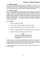
This section of the manual specifies problem areas of the balance which can occur.
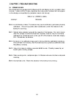
Information is contained to isolate specific problems using Table 3-1, Diagnostic Guide,
and Table 3-2, Error Codes. Follow all directions step by step. Make certain that the
work area is clean and use care when handling components of the balance.
3.2 DIAGNOSTIC GUIDE
Table 3-1 is a diagnostic guide designed to help locate the problem area quickly and
easily. To use the table, first locate the symptom that you are observing. Follow the
symptom column and review the probable cause column and remedy column. The
probable causes are listed with the most common cause first. If the first remedy does
not fix the problem, proceed on to the next remedy. Before attempting to repair the
Balance, read all chapters of this manual to familiarize yourself with the balance
components and operation. Do not attempt repairs unless you fully understand the
operation of the balance.
3.2.1 Diagnosis
1. Isolate and identify the symptom.
2. Refer to Table 3-1 Diagnostic guide and locate the symptom.
3. Follow the suggested remedies in the order that they appear.
4. Perform the indicated checks, or see the appropriate section of the manual.
5. Repair or replace the defective section of the balance.
NOTE:
If more than one symptom is observed, it is
necessary to approach one area at a time,
and also remember, that the symptoms may
be interrelated.
In the event that erratic or fluctuating weight readings are observed, it is necessary to
isolate the problem to either the mechanical area or the electronic area of the balance.
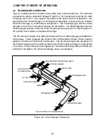
The repeatability test will quickly point out whether the Transducer (8) is operating
properly or whether the problem is due to an electronic malfunction.
If a problem arises that is not covered in this manual, contact Ohaus Corporation for
further information.
Summary of Contents for SCOUT
Page 1: ...OhausCorporation 29HanoverRoad FlorhamPark NJ 07932 0900 ELECTRONIC BALANCES SERVICE MANUAL TM...
Page 6: ...i v...
Page 10: ...1 4 CHAPTER 1 INTRODUCTION...
Page 38: ...5 2 CHAPTER 5 DRAWINGS AND PARTS LISTS...
Page 39: ...5 3 CHAPTER 5 DRAWINGS AND PARTS LISTS Figure 5 1 Exploded View of Balance 5 3 5 4...
Page 43: ...SCOUT ELECTRONIC BALANCES P N 300040 010 R1198...
Page 45: ...e e e...
Page 47: ......

