4-7
CHAPTER 4 MAINTENANCE PROCEDURES
4.2.3.1 Precision Test (Cont.)
Adjustment
If the deviation for any set of readings (using the same mass placed on the center of
the Pan) is greater than +1 count, the balance does not meet the Precision Test
specification. Inspect and correct the following areas:
1. Check for mechanical obstructions. Any foreign object touching any part
of the moving Pan linkage assembly will cause a balance to fail the
Precision Test. Inspect and correct as necessary.
2. An error in the Off-Center Load Test can affect the results of the Precision
Test. Inspect and correct if necessary. See Off-Center Load Test.
3. Foreign material or debris located in the balance between the Pan/Platform
and the Base will cause the balance to fail the test.
4. Environmental influences such as vibrations, drafts or a non-level surface can
cause failures.
4.2.3.2
Off-Center Load Test
The Off-Center Load Test is used to determine whether displayed weight values will be
affected by moving the sample to different areas of the Pan (6).
Test
1. Place 1/2 of the balance capacity in the
center of the Pan (6).
2. Press the ReZero On Switch to return the reading to zero.
3. Move the mass halfway (between the center and the edge) to the front of
the Pan (6). Note any differences in the displayed weight reading.
4. Repeat this test for the back, left, and right positions.
5. Maximum allowable change in displayed weight readings is + 1 count for
each of the four positions. If this reading is exceeded, it usually indicates a
defective Transducer (8).
4.2.3.3 Centered Load Test
This test is used to determine the linearity of the unit throughout its operating range.
The masses used to perform this test must be adjusted to ASTM Class 4 Tolerance, or
better.
NOTE:
The balance must pass the Off-Center Load
Test and Precision Test before the Centered
Load Test may be performed.
Summary of Contents for SCOUT
Page 1: ...OhausCorporation 29HanoverRoad FlorhamPark NJ 07932 0900 ELECTRONIC BALANCES SERVICE MANUAL TM...
Page 6: ...i v...
Page 10: ...1 4 CHAPTER 1 INTRODUCTION...
Page 38: ...5 2 CHAPTER 5 DRAWINGS AND PARTS LISTS...
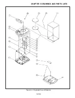
Page 39: ...5 3 CHAPTER 5 DRAWINGS AND PARTS LISTS Figure 5 1 Exploded View of Balance 5 3 5 4...
Page 43: ...SCOUT ELECTRONIC BALANCES P N 300040 010 R1198...
Page 45: ...e e e...
Page 47: ......

