4-9
CHAPTER 4 MAINTENANCE PROCEDURES
4.2.4
4.2.4
4.2.4
4.2.4
4.2.4 Down Stop Adjustment (Cont.)
Down Stop Adjustment (Cont.)
Down Stop Adjustment (Cont.)
Down Stop Adjustment (Cont.)
Down Stop Adjustment (Cont.)
4.3 REPLACEMENT OF MAJOR COMPONENTS
When using this section of the Service Manual, you will find it necessary to refer to other
sections. References are made to the Exploded View and Schematic Diagram which
are located and identified in Chapter 5, Drawings and Parts Lists.
The decision to replace any component should only be made after thoroughly diagnos-
ing the problem.
If, after the replacement of any component, the balance is still nonfunctional and no
other information on the subject is available in the Instruction Manual, contact:
Ohaus Corporation
29 Hanover Road
Florham Park, NJ 07932 USA
Tel: 973-377-9000
Fax: 973-593-0359
In the United States call Ohaus Aftermarket, toll free, 800-526-0659 between 8:00 a.m.
and 4:00 p.m. EST.
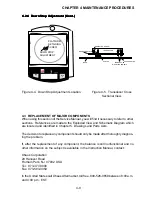
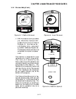
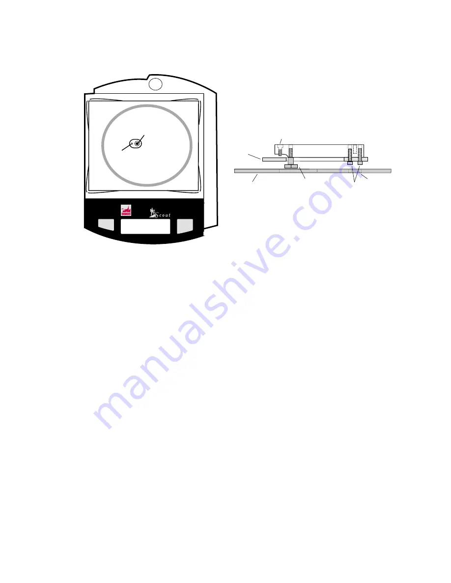
Figure 4-4. Down Stop Adjustment Location.
Mode
Off
Re Zero
On
PLATFORM
RETAINING
SCREW
DOWN STOP
ADJUSTMENT
TM
TRANSDUCER
DOWN STOP SCREW
BASE
MOUNTING PLATE
UP STOP
TRANSDUCER
MOUNTING SCREWS
ACCESS HOLES
Figure 4-5. Transducer Cross
Sectional View.
Summary of Contents for SCOUT
Page 1: ...OhausCorporation 29HanoverRoad FlorhamPark NJ 07932 0900 ELECTRONIC BALANCES SERVICE MANUAL TM...
Page 6: ...i v...
Page 10: ...1 4 CHAPTER 1 INTRODUCTION...
Page 38: ...5 2 CHAPTER 5 DRAWINGS AND PARTS LISTS...
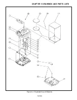
Page 39: ...5 3 CHAPTER 5 DRAWINGS AND PARTS LISTS Figure 5 1 Exploded View of Balance 5 3 5 4...
Page 43: ...SCOUT ELECTRONIC BALANCES P N 300040 010 R1198...
Page 45: ...e e e...
Page 47: ......

