background image

4-10

CHAPTER 4 MAINTENANCE PROCEDURES

4.3.1 Disassembly
This section of the manual contains detailed disassembly procedures of the balance.
Refer to Figure 5-1.  Before disassembling the balance, it should be noted that
components inside of the balance are delicate and need to be handled with care.  It is
imperative that the Transducer (8) should never be subjected to any excessive torque,
stress, or abraison as damage may result.  Once the balance has been disassembled,
any small scratch or abrasion made to any of the Individual Strain Gauges will render
the entire Transducer (8) unusable.   The Printed Circuit Board (4) contains integrated
circuits which employ CMOS technology, therefore, caution must be exercised so as not
to subject any of these components to static electricity discharge.  When servicing, a
wrist Ground Strap with a 10 Megohm series resistor to earth ground is highly
recommended.  The Printed Circuit Board (4) should be handled by grasping the edges
only and never placing fingers on any of the runs or traces.

To disassemble the balance, proceed as follows:

1. Turn the balance off and if using an AC Adapter, disconnect it from the

balance.

2. Remove the Pan (6) from the balance.

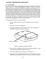
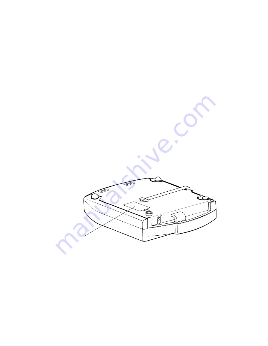
3. If a battery is being used, turn the balance over and remove the Battery

Compartment Cover (3) as shown in Figure 4-6.

Battery Compartment

Figure 4-6.  Battery Compartment Location.

4. Disconnect the  9 volt Battery from the Connector inside the balance, remove

it and replace the Battery Compartment Cover (3).

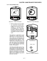
5. Remove the platform retaining Screw (22) (see Figure 4-7).

6. Remove the cover Screw (26) (see Figure 4-8).  On early production units, two

additional screws located at the bottom of the Base (1) have to be removed.

Summary of Contents for SCOUT

Page 1: ...OhausCorporation 29HanoverRoad FlorhamPark NJ 07932 0900 ELECTRONIC BALANCES SERVICE MANUAL TM...

Page 2: ...he use or misuse of this material Reproduction of this material is strictly prohibited Material in this manual is subject to change Copyright 1996 1998 Ohaus Corporation all rights reserved Registered...

Page 3: ...3 2 ON Off Circuitry 2 3 2 3 2 1 Turn On Circuitry 2 3 2 3 2 2 Turn Off Circuitry 2 3 2 3 3 Low Voltage Detector 2 4 2 3 4 Temperature A D Converter 2 4 2 3 5 Full Bridge Weight A D Convertor 2 4 2 3...

Page 4: ...own Stop Adjustment 4 8 4 3 Replacement of Major Components 4 9 4 3 1 Disassembly 4 10 4 3 1 1 Printed Circuit Board PCB 4 and Power Board Replacement 4 12 4 3 1 2 LCD Display 12 Replacement 4 12 4 3...

Page 5: ...n Gauge Transducer 2 2 2 3 Block Diagram 2 6 4 1 Front Panel Controls 4 1 4 2 Platform Retaining Screw Location 4 1 4 3 Display Turn On Sequence 4 2 4 4 Down Stop Adjustment Location 4 9 4 5 Transduce...

Page 6: ...i v...

Page 7: ...ew of the balance identifying all components and a schematic Each item on the exploded view is numbered These numbers appear in parenthesis throughout the manual after a particular part to aid in iden...

Page 8: ...on the 600g Scout 4 A total of 300 grams is required for 200g Scout down stop adjustment A total of 600 grams is required for 400g Scout down stop adjustment A total of 900 grams is required for 600g...

Page 9: ...Over range capacity 103 Stabilization time seconds 3 3 3 Sensitivity drift C 0 005 0 02 0 02 Zero point drift g C 0 03 0 5 0 5 Shift accuracy 1 2 capacity 1 2 distance g 0 01 0 1 0 1 Operating temper...

Page 10: ...1 4 CHAPTER 1 INTRODUCTION...

Page 11: ...he user an error routine is employed to indicate that the weight input is beyond the limits of the balance Various error displays indicate internal balance problems overload conditions incorrect calib...

Page 12: ...d on the top of the Transducer and uses two 1K ohm resistors on the printed circuit board to complete the bridge The Transducer consists of an aluminum beam with 2 or 4 Strain Gauges bonded at the hin...

Page 13: ...r source pressing ReZero On switch SW1 applies a ground through diode D6 resistor R22 to the base of transistor Q6 and turns on transistor Q6 When microprocessor U1 receives power an on signal is gene...

Page 14: ...measured by the duty cycle of resistor R11 which is switched from 5 volts dc and ground by U4A and U4F which act as electronic switches The duty cycle determines how much current is pulled out in this...

Page 15: ...full bridge circuit by using two 1K resistors R45 and R46 to form the other half of the bridge when two Strain Gauges are used on the Transducer The output of the half bridge Transducer is connected t...

Page 16: ...GE WEIGHT A D CONVERTER RAMP Q2 TEMPERATURE A D CONVERTER INTEGRATOR U5A COMPARATOR U3B ELECTRONIC SWITCH U4A U4F MICROPROCESSOR U1 HALF BRIDGE EMULATION HALF BRIDGE LOADCELL 9 VOLT BATTERY OR EXTERNA...

Page 17: ...manual to familiarize yourself with the balance components and operation Do not attempt repairs unless you fully understand the operation of the balance 3 2 1 Diagnosis 1 Isolate and identify the symp...

Page 18: ...eplace PC Board TABLE 3 1 DIAGNOSTIC GUIDE PROBABLE CAUSE 1 No power 2 Power Jack defective 3 Weak battery 4 Battery connector poor contact 5 PC Board defective 1 Weak battery 2 AC Adapter defective 3...

Page 19: ...ive 4 Defective transducer 1 Balance not warmed up 2 Defective Transducer 3 PC Board defective 1 Improperly calibrated 2 Overloaded 3 Defective Transducer 4 PC Board defective REMEDY 4 Set per specifi...

Page 20: ...being weighed exceeds the capacity of the balance If an error occurs when the sample is within the balance s capacity balance may be incorrectly calibrated An underload such as the pan off of the bal...

Page 21: ...th to clean all exterior surfaces When moving the balance from a storage area which is at a different temperature than the area where the balance is to be operated allow sufficient time for the balanc...

Page 22: ...e the test area is free from drafts and that the balance rests on a level and vibration free surface The masses used for the performance tests and adjustments must be adjusted to ASTM Class 4 toleranc...

Page 23: ...Span Calibration A 300 g calibration mass is supplied with the 600g balance Linearity calibration requires an additional 100g mass for 200g Balances 200g mass for 400g balances and 300g mass for 600g...

Page 24: ...MENU The User Menu permits you to activate the Auto Shut off feature available weighing units parts counting and Linearity calibration 1 With the balance off press and hold ReZero On until is display...

Page 25: ...arity Calibration Linearity Calibration Linearity Calibration Linearity Calibration 1 When the balance displays press ReZero On will be displayed followed by the value of the mass which must be placed...

Page 26: ...the following tests all the procedures starting with paragraph 4 2 must have been accomplished on the balance first Tolerance values are expressed in counts A balance which passes each of these three...

Page 27: ...l surface can cause failures 4 2 3 2 Off Center Load Test The Off Center Load Test is used to determine whether displayed weight values will be affected by moving the sample to different areas of the...

Page 28: ...Adjustment Down Stop Adjustment Use the following procedure to adjust the Downstop Screw 21 on the Transducer 8 so that the Pan 6 will bottom out when the weight on the Pan 6 is 150 of the balance s...

Page 29: ...lace any component should only be made after thoroughly diagnos ing the problem If after the replacement of any component the balance is still nonfunctional and no other information on the subject is...

Page 30: ...ponents to static electricity discharge When servicing a wrist Ground Strap with a 10 Megohm series resistor to earth ground is highly recommended The Printed Circuit Board 4 should be handled by gras...

Page 31: ...y replacement of major components The Cover 2 is secured by one Screw 26 on top of the balance and on early production units two screws at the bottom of the Base 1 The Platform 5 is secured by one Scr...

Page 32: ...ing from the Transducer 8 from the connector on the Printed Circuit Board 4 as shown in Figure 5 1 3 Unclip the Printed Circuit Board 4 from the Base 1 and unclip the Power Board from the Base 1 Remov...

Page 33: ...LCD and position the LCD on the Cover 2 Fasten the LCD Display 12 into the proper position 7 Position the Cover 2 against the Base 1 as shown in Figure 4 9 and using both hands grasp the ribbon cable...

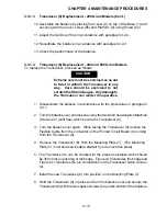
Page 34: ...then remove the Transducer 8 from the Mounting Plate 7 The Mounting Plate 7 is not field serviceable do not try to remove this plate 6 Install the new Transducer 8 Into position on the Mounting Plate...

Page 35: ...cordance with the procedures in paragraph 4 3 1 2 Turn the balance over and loosen evenly the two Allen head captive Machine Screws 22 until free which secure the Transducer 8 3 Turn the balance over...

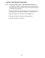
Page 36: ...able from the Transducer 8 into the connector provided for it on the Printed Circuit Board 4 10 Assemble the balance by placing the Cover 2 on top of the Base 1 and securing with the Cover screw 26 an...

Page 37: ...is replaced the balance must be thoroughly checked after the replacement is made The balance MUST meet the parameters of all applicable specifi cations in this manual Iffurthertechnicalinformationisn...

Page 38: ...5 2 CHAPTER 5 DRAWINGS AND PARTS LISTS...

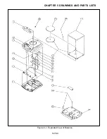
Page 39: ...5 3 CHAPTER 5 DRAWINGS AND PARTS LISTS Figure 5 1 Exploded View of Balance 5 3 5 4...

Page 40: ...22 MF 3 92K R39 MF 274K C16 AE 22uF MPS6515 Q1 MPS6515 Q5 R21 MF 1 5K R41 MF 2 74K 2N4403 Q6 R23 MF 15K C10 CM 1U C8 CM 1U C18 AE 22uF J5 J6 E1A E2A E3 E3A E2 E1 NC 2 3 1 J3 R34 MF 10M V5 V5 C12 CM 10...

Page 41: ...010 Pan Support Round 5 300020 010 Pan Support Square 6 77064 00 Pan Round Stainless Steel 4 dia 200g Models 6 300007 010 Pan Square 400g and 600g Models 7 300009 010 Mounting Plate See Note 3 8 3000...

Page 42: ...for 400g or 600g Models For 200g Models Transducer Kit must be replaced NOTES 1 Transducers replacement kit for 200 grams include Transducer and a replacement EEPROM U6 2 When replacing the LCD the F...

Page 43: ...SCOUT ELECTRONIC BALANCES P N 300040 010 R1198...

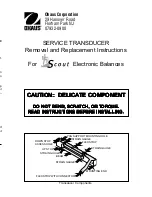
Page 44: ...TCH TCH OR OR OR OR OR T T T T TORQ ORQ ORQ ORQ ORQUE UE UE UE UE READ INSTR READ INSTR READ INSTR READ INSTR READ INSTRUCTIONS BEFORE INST UCTIONS BEFORE INST UCTIONS BEFORE INST UCTIONS BEFORE INST...

Page 45: ...e e e...

Page 46: ...lex cable see Figure 4 6 Locate the transducer and unplug the flex cable from the PC board con nector The top of the connector has a lip which must be lifted up on both sides to release the flexcable...

Page 47: ......

Page 48: ...d CT Transfer solder link settings S1 S4 Transfer IC EEPROM U2 Scout Insure that R40 is not installed Transfer IC EEPROM U6 Navigator Transfer IC EEPROM U4 TS TP Precision Standard Plus Transfer IC EP...

Page 49: ...EPROM IC1 Transfer IC EPROM IC16 Power Supply PCB Transfer IC EPROM IC8 Transfer IC EEPROM IC3 Transfer IC Transducer ID IC12 Looks like a transistor MB200 Balance PCB Transfer IC EPROM U5 Transfer R1...

Page 50: ...the weight to point D and record the reading If the reading at point A is negative file at points 1 and 4 AT AN ANGLE If the reading at point B is negative file at points 1 and 2 STRAIGHT ACROSS If th...

Page 51: ...ge Perform a linearity cal If this fails replace the transducer Error 4 Check the downstop screw Wrong cal weight used Perform a linearity cal If this fails replace the transducer No Display Check ope...

Reviews: