4-13
CHAPTER 4 MAINTENANCE PROCEDURES
4.3.1.2
LCD Display (12) Replacement (Cont.)
Refer to the parts list in section 5 for the kit number which contains both parts.
To replace the LCD, proceed as follows:
1. Disassemble the balance in accordance with the procedures in paragraph
4.3.1.
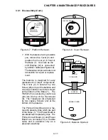
2. With the Cover (2) folded back so that the inside of the balance is exposed,
grasp the ribbon cable of the LCD using both hands and remove the cable
from the socket on the Printed Circuit Board (4) as shown in Figure 4-9. The
end of the ribbon cable is a connector.
3. Turn the Cover (2) over and remove the Function Label (13). Remove all
traces of adhesive from the Cover (2).
4. Remove the defective LCD Display (12) from the Cover (2). Remove all
traces of adhesive from the Cover (2).
5. Route the cable from the new LCD through the opening in the Cover (2).
6. Place the replacement LCD Display (12) into position on the Cover (2). Peel
off the adhesive back from the LCD and position the LCD on the Cover (2).
Fasten the LCD Display (12) into the proper position.
7. Position the Cover (2) against the Base (1) as shown in Figure 4-9 and using
both hands grasp the ribbon cable from the LCD and firmly press the cable
into the connector on the Printed Circuit Board (4). Make sure that the cable
is firmly seated in the connector.
8. Assemble the balance by placing the Cover (2) on top of the Base (1) and
securing with the Cover screw (26) and Platform (5) using Screw (22).
9. Place the new Function Label (13) into position on the Cover (2) to see how
the label fits. Then, remove the adhesive back and carefully fasten the Label
into position.
4.3.1.3
Transducer (8) Replacement - 200 Gram Models
On the 200 gram models, an EEPROM is supplied in the kit. This EEPROM U6 must
be replaced on the Printed Circuit Board (4) when the Transducer (8) is replaced. To
replace the Transducer (8) and EEPROM U6, proceed as follows:
CAUTION
Extreme care must be exercised so as not
to twist or deform the Transducer in any
way. Care should be exercised to not
scratch the Strain Gauges. Any damage to
the Transducer can render it inoperative.
Summary of Contents for SCOUT
Page 1: ...OhausCorporation 29HanoverRoad FlorhamPark NJ 07932 0900 ELECTRONIC BALANCES SERVICE MANUAL TM...
Page 6: ...i v...
Page 10: ...1 4 CHAPTER 1 INTRODUCTION...
Page 38: ...5 2 CHAPTER 5 DRAWINGS AND PARTS LISTS...
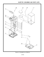
Page 39: ...5 3 CHAPTER 5 DRAWINGS AND PARTS LISTS Figure 5 1 Exploded View of Balance 5 3 5 4...
Page 43: ...SCOUT ELECTRONIC BALANCES P N 300040 010 R1198...
Page 45: ...e e e...
Page 47: ......


