5-1
CHAPTER 5 DRAWINGS AND PARTS LISTS
5.1 DRAWINGS
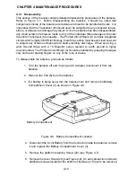
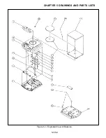
This section of the manual contains an exploded view and schematic diagram for Scout
balances, 200g, 400g and 600g. The exploded view drawing is designed to identify the
parts which can be serviced on the balance in the field.
NOTE:
In all cases where a part is replaced, the
balance must be thoroughly checked after the
replacement is made. The balance MUST
meet the parameters of all applicable specifi-
cations in this manual.
If further technical information is needed, in the United States call Ohaus Aftermarket toll-
free 1-800-526-0659 between 8.00 a.m. and 4.00 p.m. EST. An Ohaus factory service
technician will be available to provide assistance. Outside the U.S.A., please contact:
Ohaus Corporation
29 Hanover Road
Florham Park, NJ 07932, USA
Tel: (973) 377-9000,
Fax: (973) 593-0359
Summary of Contents for SCOUT
Page 1: ...OhausCorporation 29HanoverRoad FlorhamPark NJ 07932 0900 ELECTRONIC BALANCES SERVICE MANUAL TM...
Page 6: ...i v...
Page 10: ...1 4 CHAPTER 1 INTRODUCTION...
Page 38: ...5 2 CHAPTER 5 DRAWINGS AND PARTS LISTS...
Page 39: ...5 3 CHAPTER 5 DRAWINGS AND PARTS LISTS Figure 5 1 Exploded View of Balance 5 3 5 4...
Page 43: ...SCOUT ELECTRONIC BALANCES P N 300040 010 R1198...
Page 45: ...e e e...
Page 47: ......

