5-8
CHAPTER 5 DRAWINGS AND PARTS LISTS
TABLE 5-1. REPLACEMENT PARTS LIST (Cont.)
KEY NO.
PART NO.
DESCRIPTION
22
H3207-03
Screw, 8-32 x 3/8" Btn Head Cap (3)
23
E1103-27
Screw, 4-40 x 5/32" Phillips Pan Head
26
E2107-24
Screw, Self Tapping #6, 6-20 x 3/4" Pan Head
27
90580-00
Power Jack
---
90524-66
AC Adapter 100/120 V ac US Plug (not shown)
---
90524-63
AC Adapter 220 V ac Euro Plug (not shown)
---
90524-64
AC Adapter 240 V ac UK Plug (not shown)
---
90524-65
AC Adapter 240 V ac Australian Plug (not shown)
---
390007-010
Switch
---
90664-02
IC, EEPROM U6 (Must be programmed for 400g or
600g Models. For 200g Models, Transducer Kit must
be replaced.)
NOTES:
1. Transducers replacement kit for 200 grams include Transducer and a
replacement EEPROM, U6.
2. When replacing the LCD, the Function label must also be replaced,
Kit No.300015-010 includes both parts.
3. Part is not field serviceable.
4. In all cases where a part is replaced, the balance shall be thoroughly
checked after the replacement is made. The balance must meet the
parameters of all applicable specifications in this manual.
5. Items 9 and 10 shown on Figure 5-1 are assembled as part of the
Transducers.
6. Ohaus replacement parts warranty only applies to parts purchased
from Ohaus Corporation.
7. Transducer kits are supplied with Upstop and Downstop screws.
Summary of Contents for SCOUT
Page 1: ...OhausCorporation 29HanoverRoad FlorhamPark NJ 07932 0900 ELECTRONIC BALANCES SERVICE MANUAL TM...
Page 6: ...i v...
Page 10: ...1 4 CHAPTER 1 INTRODUCTION...
Page 38: ...5 2 CHAPTER 5 DRAWINGS AND PARTS LISTS...
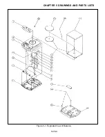
Page 39: ...5 3 CHAPTER 5 DRAWINGS AND PARTS LISTS Figure 5 1 Exploded View of Balance 5 3 5 4...
Page 43: ...SCOUT ELECTRONIC BALANCES P N 300040 010 R1198...
Page 45: ...e e e...
Page 47: ......


