Ohaus Corporation
29 Hanover Road
Florham Park NJ
07932-0900
Ohaus Corporation
29 Hanover Road,
Florham Park, NJ 07932, USA
Tel: (973) 377-9000,
Fax: (973) 593-0359
With offices worldwide.
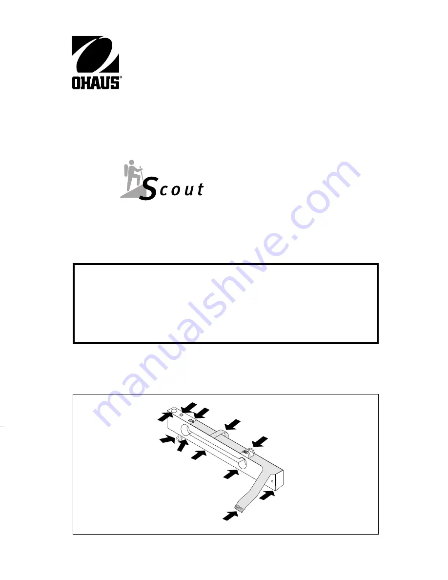
Transducer Components
CA
CA
CA
CA
CAUTION:
UTION:
UTION:
UTION:
UTION: DELICA
DELICA
DELICA
DELICA
DELICATE COMPONENT
TE COMPONENT
TE COMPONENT
TE COMPONENT
TE COMPONENT
DO NO
DO NO
DO NO
DO NO
DO NOT BEND
T BEND
T BEND
T BEND
T BEND,,,,, SCRA
SCRA
SCRA
SCRA
SCRATCH,
TCH,
TCH,
TCH,
TCH, OR
OR
OR
OR
OR T
T
T
T
TORQ
ORQ
ORQ
ORQ
ORQUE.
UE.
UE.
UE.
UE.
READ INSTR
READ INSTR
READ INSTR
READ INSTR
READ INSTRUCTIONS BEFORE INST
UCTIONS BEFORE INST
UCTIONS BEFORE INST
UCTIONS BEFORE INST
UCTIONS BEFORE INSTALLING.
ALLING.
ALLING.
ALLING.
ALLING.
Down Stop Adjustment
Down Stop Adjustment
Down Stop Adjustment
Down Stop Adjustment
Down Stop Adjustment
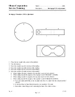
Use the following procedure to adjust the down stop screw so that the pan will
“bottom out” when the weight on the pan is 150% of the balance’s capacity.
1.
Place a mass on the pan equal to 100% of the balance capacity.
2.
Gently press down on the pan and verify that there is downward movement.
3.
Place a mass on the pan equal to 150% balance capacity .
4.
Gently press down on the pan and check for downward movement. If the pan
does not move downward, the down stop adjustment is correct. Proceed to
step 7.
5.
If the pan moves down when pressed, remove the pan, rotate the down stop
screw 1/8 turn clockwise using a small flat blade screwdriver (see Figure 1 for
down stop location and Figure 5 which is cross sectional view of the trans-
ducer).
6.
Repeat steps 4 and 5 as necessary until there is no downward movement.
7.
Repeat the entire procedure to verify that with 100% capacity on the pan, it
moves down when pressed, and with 150% capacity on the pan, it does not
move when pressed.
8.
Refer to the Instruction Manual and calibrate the balance after installation.
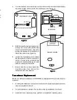
TRANSDUCER
DOWN STOP SCREW
BASE
MOUNTING PLATE
UP STOP
TRANSDUCER
MOUNTING SCREWS
ACCESS HOLES
Figure 5
Figure 5
Figure 5
Figure 5
Figure 5
SERVICE TRANSDUCER
Removal and Replacement Instructions
For Electronic Balances
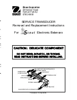
DOWN STOP
ACCESS HOLE
MOUNTING END
FLEX STRIP WITH CONNECTOR
STRAIN GAUGE
BEAM
STRAIN GAUGE
PAN SUPPORT MOUNTING HOLE
STRAIN GAUGE
FLEX STRIP
STRAIN GAUGE
UP STOP
TM
P/N 300035-011 © Ohaus Corporation 1997, 1999 all rights reserved.
Summary of Contents for SCOUT
Page 1: ...OhausCorporation 29HanoverRoad FlorhamPark NJ 07932 0900 ELECTRONIC BALANCES SERVICE MANUAL TM...
Page 6: ...i v...
Page 10: ...1 4 CHAPTER 1 INTRODUCTION...
Page 38: ...5 2 CHAPTER 5 DRAWINGS AND PARTS LISTS...
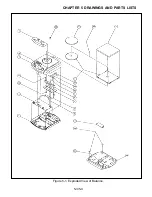
Page 39: ...5 3 CHAPTER 5 DRAWINGS AND PARTS LISTS Figure 5 1 Exploded View of Balance 5 3 5 4...
Page 43: ...SCOUT ELECTRONIC BALANCES P N 300040 010 R1198...
Page 45: ...e e e...
Page 47: ......

