Introduction
Introduction
Introduction
Introduction
Introduction
The Service Transducer Kit for the 200 gram model contains a transducer and an
EEPROM.
CAUTION:
CAUTION:
CAUTION:
CAUTION:
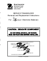
CAUTION: The service transducer is a delicate component. Use extreme caution
when handling it. Do not subject the transducer to abrupt shock or bend the flex
cable.
Tools Required
Tools Required
Tools Required
Tools Required
Tools Required
•
Phillips head screwdriver
•
Small flat blade (1/16 inch) screwdriver
•
3/32 inch hex Allen head wrench
•
200 g and 300 g masses for 200 gram balances
•
400 g and 600 g masses for 400 gram balances
•
600 g and 900 g masses for 600 gram balances
Transducer Removal
Transducer Removal
Transducer Removal
Transducer Removal
Transducer Removal
Before beginning, make sure the balance is OFF and unplugged.
1.
Remove the pan.
2.
Remove the platform retaining screw(see Figure 1).
Mode
Off
Re Zero
On
PLATFORM
RETAINING
SCREW
DOWN STOP
ADJUSTMENT
TM
Figure 1
Figure 1
Figure 1
Figure 1
Figure 1
Mode
Off
Re Zero
On
COVER SCREW
TRANSDUCER
TM
Figure 2
Figure 2
Figure 2
Figure 2
Figure 2
3.
Remove the cover screw (see Figure 2).
4.
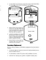
Turn the balance over and loosen evenly until free the two Allen head captive
mounting screws which secure the transducer (see Figure 3).
TRANSDUCER
BOTTOM OF UNIT
CAPTIVE MOUNTING SCREWS
UP STOP
Figure 3
Figure 3
Figure 3
Figure 3
Figure 3
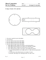
PC BOARD
DISPLAY
POWER BD
BATTERY
COMPARTMENT
TRANSDUCER
MOUNTING PLATE
INSIDE COVER
CLIPS
U6
EEPROM
Figure 4
Figure 4
Figure 4
Figure 4
Figure 4
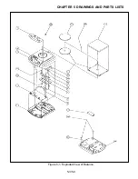
5.
With the balance facing towards you,
remove the cover and position the
cover in front of the base. Use care
as the LCD display is connected by a
ribbon flex cable (see Figure 4).
6.
Locate the transducer and unplug
the flex cable from the PC board con-
nector. The top of the connector has
a lip which must be lifted up on both
sides to release the flexcable.
7.
Ensure that the up stop clears the
mounting plate, then remove the
transducer from the balance.
Transducer Replacement
Transducer Replacement
Transducer Replacement
Transducer Replacement
Transducer Replacement
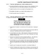
NOTE: On 200 gram balances, an EEPROM is supplied with the kit and must be
replaced.
1.
On 200 gram balances, remove IC U6 from the PC board and replace with the
new one supplied in the kit.
2.
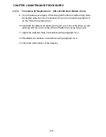
For all transducers, install in the reverse order as explained in removal.
3.
Install the cover retaining screw, platform, and platform retaining screw.
Summary of Contents for SCOUT
Page 1: ...OhausCorporation 29HanoverRoad FlorhamPark NJ 07932 0900 ELECTRONIC BALANCES SERVICE MANUAL TM...
Page 6: ...i v...
Page 10: ...1 4 CHAPTER 1 INTRODUCTION...
Page 38: ...5 2 CHAPTER 5 DRAWINGS AND PARTS LISTS...
Page 39: ...5 3 CHAPTER 5 DRAWINGS AND PARTS LISTS Figure 5 1 Exploded View of Balance 5 3 5 4...
Page 43: ...SCOUT ELECTRONIC BALANCES P N 300040 010 R1198...
Page 45: ...e e e...
Page 47: ......


