background image

CHAPTER 1  

GETTING STARTED


Ohaus Corporation  www.ohaus.com 

1-8 

3000 T32ME & MC Indicator Service Manual 

1.8  RS232 INTERFACE CONNECTION 

The T32 has a bi-directional RS232 interface for communication with printers and computers. 
When communication is used, data can be output various ways, depending on PRINT menu 
settings. 

For RS232 cable connections, see Section 1.5.2, page 1-5. 

1.8.1  Setting Communications Parameters 

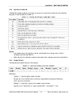
The T32 Indicator’s default communication parameters are baud rate 9600 bits per second 
(bps), 8 databits, no parity

,

 Handshake XON/XOFF, Stable Only Off, and Autoprint Off.   

To change these settings use the PRINT menu, as follows: 

1.  Press and hold 

TARE/Menu

 until 

C.A.L. 

appears.  Press 

No

.  

S.E.t.U.P

 appears.   

Press 

No

.  

r.E.A.d

 appears.  Press 

No

.  

M.O.d.E

 appears.  Press 

No.


U.N.I.t 

appears.  

Press 

No

.  

P.r.i.n.t 

appears.  Press 

Yes

rESEt 

appears.  Press 

No.


2. 

bAUd 

appears.  Press 

Yes

.  


3.  The default Baud rate setting, 

9600 

bps, appears.  To change the setting, press 

No.


The menu cycles to the next setting each time you press No: first 9600, then 300, 600, 
1200, 2400, 4800, and 9600 again.  Press Yes when the desired setting appears.  bAUd 
appears again.  Press No.   

4. 

PAritY 

appears.  Press 

Yes

.  The default Parity setting, 

NONE

, appears.  To change the setting, press 

No

.


5.  The menu cycles to the next setting each time you press No: 

first 7 Even, then 7 Odd, 7 None, and 8 None again.  Press 

Yes


to accept a setting.  

PAritY 

appears again.  Press 

No

.


6. 

StOP 

appears.  Press 

Yes

. The default Stop Bit setting, 

1

, appears.   

To change the setting, press 

No

.


7.  The menu toggles to the next setting each time you press No: 

first 1, then 2, then 1 again.  Press 

Yes

 when the desired setting 

appears.  

StOP 

appears again.  Press 

No

.


8. 

HANd 

appears.  Press 

Yes

.  The default Handshake setting, 

On-Off

 (Xon/Xoff), 

appears.  To change the setting, press 

No

.


9.  The menu toggles to the next setting each time you press No: first Off, 

then On-Off, then Off again.  Press 

Yes

 when the desired setting 

appears.  

HANd 

appears again.  Press 

No

.


10. 

StAbLE 

appears.  Press 

Yes

.  The Stable setting allows the Indicator to print values 

only when the stability criteria are met.  To choose 

ON

, press 

Yes

.  If you press 

No

Off


appears.  Press 

Yes 

to accept a setting.  Then 

StAbLE 

appears.  Press 

No

.  


11. 

A.Print

 appears.  Press 

Yes

.  Auto Print sets printing to occur each 

time stability criteria are met (

ON.StAB

), or at a defined interval 

(

INtEr

), or continuously (

CONt

).  The default setting is 

Off

.  Press 

No


until the preferred setting appears. Then press 

Yes

.  

A.Print

 appears.  

Press 

No

.  

INtEr

 appears.   

12. If 

INtEr 

was selected, use the 

INtEr 

sub-menu to set the interval, from 1 to 3600 

seconds.  Press 

No

 to advance, 

Back

 to regress, and 

Yes

 to accept a setting.  After you 

press 

Yes

INtEr 

appears again. Press 

No

 twice, then 

Yes

 when 

End

 appears, 

No

 when 

P.r.i.n.t 

appears, 

No

 again, and 

Yes

 when End appears again to exit menu mode.


Summary of Contents for T32ME

Page 1: ...SERVICE MANUAL 3000 Series T32ME T32MC Indicators T32ME T32MC Ohaus Corporation 7 Campus Drive Suite 310 Parsippany NJ 07054 973 377 9000...

Page 2: ......

Page 3: ...ate at the time of publication but Ohaus Corporation assumes no liability arising from the use or misuse of this material Reproduction of this material is strictly prohibited Material in this manual i...

Page 4: ......

Page 5: ...G 2 1 Introduction 2 1 2 2 Visual Inspection 2 1 2 3 Error Codes 2 2 2 4 Problem Solver 2 3 CHAPTER 3 MAINTENANCE PROCEDURES 3 1 Preventive Maintenance 3 1 3 1 1 Preventive Maintenance Checklist 3 1 3...

Page 6: ...Parts 5 3 5 2 T32ME LED Indicator Housing Internal Parts 5 5 A 1 Setup Calibration Values A 3 B 1 Geographical Adjustment Values B 1 LIST OF ILLUSTRATIONS FIGURE NO TITLE 1 1 Four screws on rear panel...

Page 7: ...T32ME MC Indicators Service Manual iii Ohaus Corporation www ohaus com FIGURE NO TITLE Page No 3 11 Main PCB 3 6 5 1 Series 3000 T32MC Indicator Housing Internal Parts 5 2 5 1 Series 3000 T32ME Indica...

Page 8: ...TABLE OF CONTENTS Ohaus Corporation www ohaus com iv 3000 Series T32ME MC Indicators Service Manual...

Page 9: ...ational test segment display test performance tests and adjustments Chapter 5 Drawings and Parts Lists Contains exploded views of T32 Indicators identifying all serviceable components Before servicing...

Page 10: ...pecial Tools and Test Equipment List 1 Ohaus Scale Base 2 Load Cell Simulator optional 3 Computer with RS232 Interface for testing the RS232 communications 4 RS232 Interface cable 25 pin PN 80500524 9...

Page 11: ...digit 7 segment backlit LCD 0 8 20mm digit height 6 digit 7 segment Red LED Backlight White LED Keypad 4 button membrane switches Load Cell Excitation Voltage 5V DC Load Cell Drive Up to 4 x 350 ohm l...

Page 12: ...the threaded knobs holding the Indicator by hand CAUTION ELECTRICAL SHOCK HAZARD REMOVE ALL POWER CONNECTIONS TO THE INDICATOR BEFORE SERVICING OR MAKING INTERNAL CONNECTIONS Remove the four screws fr...

Page 13: ...Jumpers W1 and W2 For load cells with a ground shield wire connect the shield to the center position GND Figure 1 4 Jumpers 1 5 2 RS232 Interface Each model has a standard 9 pin D style RS232 connect...

Page 14: ...ges the weighing unit Mode Allows changing the application mode Press and hold allows scrolling through modes Menu Enter the User menu Extended press View the Audit Trail event counters Menu Function...

Page 15: ...Menu Mode press and hold the TARE Menu button until MENU appears on the display The first upper level menu appears on the display Use Yes No Back and Exit to navigate in Menu Mode Yes Allows entry int...

Page 16: ...No first 7 Even then 7 Odd 7 None and 8 None again Press Yes to accept a setting PAritY appears again Press No 6 StOP appears Press Yes The default Stop Bit setting 1 appears To change the setting pre...

Page 17: ...t g kg lb oz lb oz xU Set scale to unit x 1 g 2 kg 3 lb 4 oz 5 lb oz PV Version print name software revision and LFT ON if LFT is set ON Esc R Global reset to reset all menu settings to the original f...

Page 18: ...set the LFT menu item to OFF as follows 1 Press and hold TARE Menu until C A L appears then press No 2 S E t U P appears Press Yes 3 rESEt appears Press No 4 LFt appears Press Yes 5 OFF appears Press...

Page 19: ...note their condition 1 Examine the Indicator for signs of abuse such as a cracked top cover or base damage from liquids cracks on corners which may suggest the unit was dropped 2 Open the Indicator by...

Page 20: ...necessary Error 8 3 Weight reading exceeds Overload limit Reduce load on scale If error continues Test the PCB replace if necessary Error 8 4 Weight reading below Underload limit Recalibrate If error...

Page 21: ...le exceeds allowable limits Load on Scale is not stable Load Cell is damaged PCB is damaged Remove load on Scale Wait for load to become stable Replace Load Cell Test Replace PCB Section 3 6 Poor accu...

Page 22: ...CHAPTER 2 TROUBLESHOOTING Ohaus Corporation www ohaus com 2 4 3000 Series T32ME MC Indicators Service Manual...

Page 23: ...side using a cloth dampened with a mild detergent CAUTION DO NOT USE CHEMICAL CLEANERS OR SOLVENTS OF ANY TYPE SOME CLEANERS ARE ABRASIVE AND MAY AFFECT THE SCALE S FINISH 3 Check the Power Cord for b...

Page 24: ...wer supply jack Place DVM probes into rear sockets volts dc with power off and 7 2 7 5 volts dc with power on 4 Using a DVM measure the excitation voltage EXE and EXE in Figures 3 2 and 3 3 The readin...

Page 25: ...oad Cell assembly non standard proprietary connection Figure 3 3 shows the difference between standard and non standard strain gauge load cells The wires on the standard strain gauge load cell left co...

Page 26: ...receives a voltage excitation from a regulated power source in the Indicator and returns a low voltage millivolt mV signal relative to the force applied The Load Cell signal is converted to a numeric...

Page 27: ...nted Circuit Board PCB Figure 3 11 Load Cell wiring 3 3 2 3 How to Operate Simulators The function of a Simulator is to simulate the output of a full bridge Load Cell allowing the scale to be separate...

Page 28: ...dicator housing Also remove the battery 2 Disconnect the Load Cell cable from the PC Board 3 With the Simulator set to zero attach it to the PCB See Figure 3 11 4 Connect a known good AC Adapter to th...

Page 29: ...gures 3 2 and 3 3 5 Carefully disconnect the AC power and battery connectors and the Membrane Switch cable 6 Remove the four screws from the PCB 7 Lift out the PCB CAUTION When handling the PCB grasp...

Page 30: ...the Top Cover and remove all traces of adhesive 3 Remove the protective backing from the back of the new Function Label Carefully position it on the Top Housing starting at the bottom of the cover Us...

Page 31: ...he software revision and then goes into weighing mode 4 If all of the displays appear normal in this test continue with the next test If the display did not appear check the AC adapter output and repe...

Page 32: ...r to each setting between 0 2 mv V and 1 8 mv V The indicator reading should be stable and linear throughout the range of settings 4 5 Calibration Retention Test This test checks that the Indicator re...

Page 33: ...r in the field NOTE In all cases where a part is replaced the indicator must be thoroughly checked after the replacement is made The indicator MUST meet the parameters of all applicable specifications...

Page 34: ...ISTS DIAGRAMS Ohaus Corporation www ohaus com 5 2 3000 Series T32ME MC Indicators Service Manual 5 1 3000 SERIES T32MC LCD INDICATOR HOUSING INTERNAL PARTS Figure 5 1 Series 3000 T32MC Indicator Housi...

Page 35: ...OR HOUSING INTERNAL PARTS TABLE 5 1 T32MC LCD INDICATOR HOUSING INTERNAL PARTS Drawing Item Description 1 LFT Kit 2 Function Label 3 Housing Top 5 LCD W backlight 7 Main PCB 10 Bottom Housing 11 Knobs...

Page 36: ...LISTS DIAGRAMS Ohaus Corporation www ohaus com 5 4 3000 Series T32ME MC Indicators Service Manual 5 2 3000 SERIES T32ME INDICATOR HOUSING INTERNAL PARTS Figure 5 1 Series 3000 T32ME Indicator Housing...

Page 37: ...ICATOR HOUSING INTERNAL PARTS TABLE 5 2 T32ME LED INDICATOR HOUSING INTERNAL PARTS Drawing Item Description 1 LFT Kit 2 Function Label 3 Housing Top 5 LED 7 Main PCB 10 Bottom Housing 11 Knobs set of...

Page 38: ...CHAPTER 5 PARTS LISTS DIAGRAMS Ohaus Corporation www ohaus com 5 6 3000 Series T32ME MC Indicators Service Manual...

Page 39: ...again after turning it off it is necessary to have the Indicator locked and sealed by local Weights and Measures authorities 4 If the Calibration Menu is locked in the Menu Lock submenu turn it back o...

Page 40: ...pan calibration was successful the scale exits to the active weighing mode and displays the actual weight value A 3 LINEARITY CALIBRATION Linearity calibration uses three calibration points the first...

Page 41: ...0 1 5 10 15 20 25 30 40 50 60 75 100 50 100 120 0 01 0 02 0 05 0 1 0 02 0 05 0 1 5 10 15 20 25 30 40 50 60 75 100 120 60 120 150 0 01 0 02 0 05 0 1 0 05 0 1 5 10 15 20 25 30 40 50 60 75 100 120 150 7...

Page 42: ...2000 2500 3000 5000 2500 5000 6000 0 5 1 2 5 1 2 5 5 10 15 20 25 30 40 50 60 75 100 120 150 200 250 300 400 500 600 750 1000 1200 1500 2000 2500 3000 5000 6000 2500 5000 7500 0 5 1 2 5 2 5 5 10 15 20...

Page 43: ...JUSTMENT VALUES Elevation above sea level in meters 000 325 325 650 650 975 0975 1300 1300 1625 1625 1950 1950 2275 2275 2600 2600 2925 2925 3250 3250 3575 Elevation above sea level in feet Geographic...

Page 44: ...85 45 85 45 90 00 15 15 16 16 17 17 18 18 19 19 20 20 21 21 22 22 23 23 24 24 25 25 26 26 27 27 28 28 29 29 30 30 31 14 15 15 16 16 17 17 18 18 19 19 20 20 21 21 22 22 23 23 24 24 25 25 26 26 27 27 28...

Page 45: ......

Page 46: ...80253153 P N 80253153 SERVICE MANUAL 3000 SERIES T32MC T32ME INDICATORS...

Reviews: