CHAPTER 3 REPAIR PROCEDURES
3000 Series T32ME & MC Indicators Service Manual
3-3
Ohaus Corporation www.ohaus.com
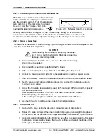
3.3.2.1 Simulators Can Substitute for Standard Strain Gauge Load Cells
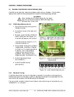
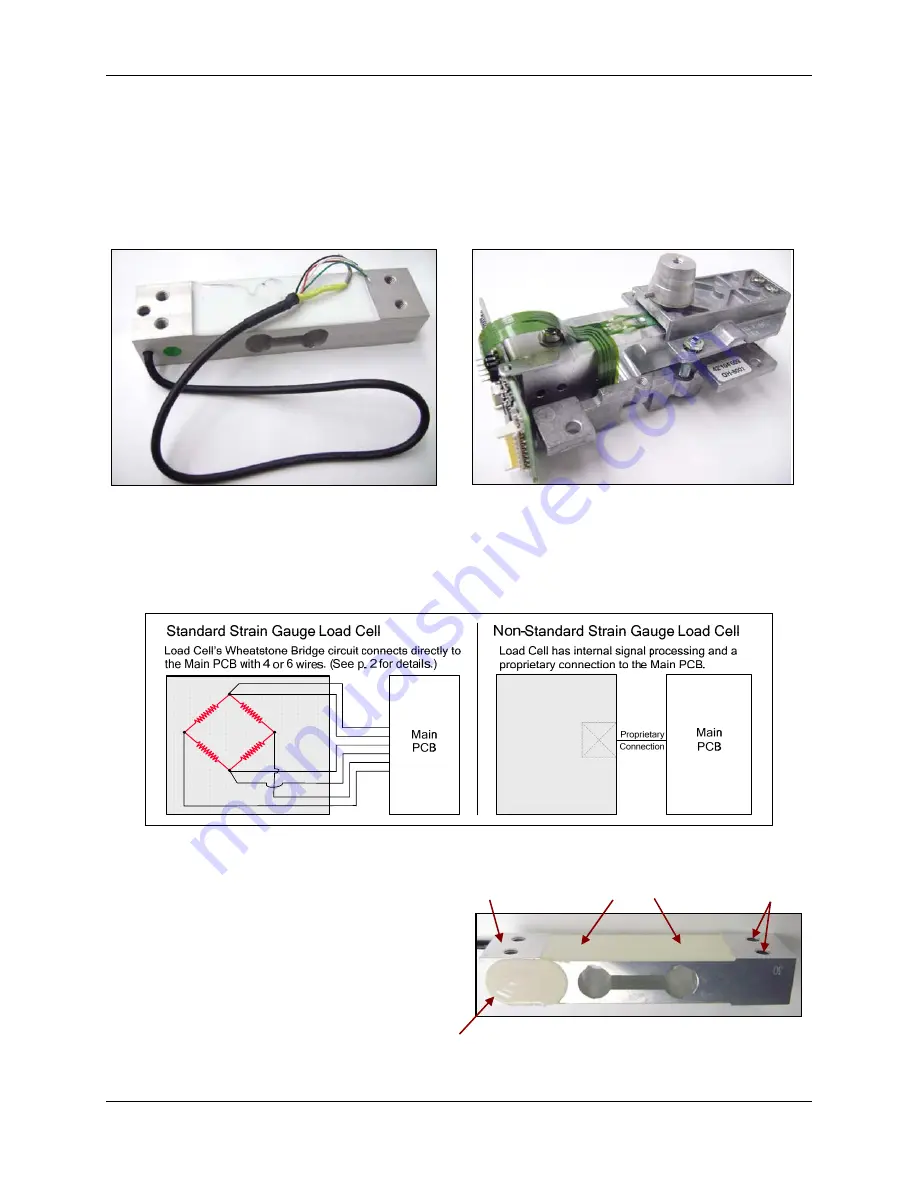
Strain gauge simulators can only substitute for standard strain gauge load cells. (Figure 3-4.)
The following explanation applies to strain gauges with Wheatstone Bridge circuitry, connecting
directly to terminals on a Main Printed Circuit Board (PCB). Some strain gauges have internal
signal processing, such as the Adventurer Pro (Figure 3-5). A simulator cannot be substituted
for this type of strain gauge.
Figure 3-4. Standard Strain Gauge Load
Cell.
Figure 3-5. Strain Gauge Load Cell assembly
non-standard (proprietary) connection.
Figure 3-3 shows the difference between standard and non-standard strain gauge load cells.
The wires on the standard strain gauge load cell (left) connect directly to the Main PCB.
The non-standard strain gauge load cell (right) has a proprietary connection.
Figure 3-6. Connection difference on standard and non-standard strain gauge load cells.
3.3.2.2 How Strain Gauge Load Cells Operate
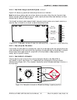
Load Cells convert force into a signal. The
Strain Gauge Load Cell is a metal beam with
holes drilled in it. Strain gauges are affixed to
the beam at the top and bottom to measure
changes in the beam due to deflection. The
gauges sense very small deflections in the
metal caused by the load applied to the cell.
Figure 3-7. Typical Strain Gauge Load Cell.
Internal PCB
Beam
Strain Gauges
Attachment points
to Platform
Summary of Contents for T32ME
Page 2: ......
Page 4: ......
Page 45: ......
Page 46: ...80253153 P N 80253153 SERVICE MANUAL 3000 SERIES T32MC T32ME INDICATORS...


