CHAPTER 1
GETTING STARTED
1.7 OPERATION
This section contains information on the basic operation of the Indicator. An exploded view
drawing is included in Chapter 5 which identifies all components of the indicator. The
descriptions in this manual refer to the names of the components identified in the exploded view
drawing with the numbered callout.
1.7.1 Power Supply
Both models have an Internal Universal Power Supply, 100-240 VAC / 50-60 Hz, and plug into a
standard, properly grounded electrical outlet.
The T51P indicator can also be operated on six alkaline
batteries (not supplied) when AC power is not available.
(An optional rechargeable battery system is also available.)
The Indicator will automatically switch to battery operation if
there is power failure or the power cord is removed. The
indicator can operate for up to 80 hours on battery power.
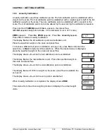
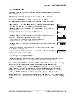
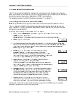
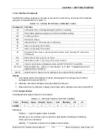
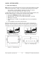
During battery operation, the battery charge symbol indicates
the battery status. The indicator will automatically turn-off
when the batteries are fully discharged.
0 % - 5 % charged
5 % - 25 % charged
26 % - 50 % charged
51 % - 75 % charged
76 % - 100 % charged
Figure 1-8. Battery charge
symbol.
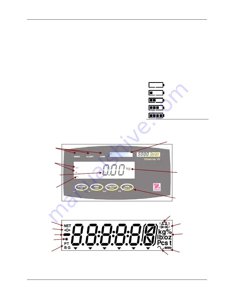
1.8 OVERVIEW OF THE CONTROLS
Capacity label
window
Under, Accept
& Over LEDs
Stability &
Zero symbols
Kilogram,
Pound, &
Ounce symbols
(For complete list,
see Figure 1-7.)
7-segment, 6-digit
LED display
Brutto, Gross
symbols
(For complete list,
see Figure 1-8.)
Control Buttons
Figure 1-9. T51 Display.
1.8.1 OVERVIEW OF THE DISPLAY INDICATORS
Scale symbol
(not used)
Center of Zero
indicator
Negative symbol
Net symbol
Range symbol
Kilogram, Gram,
Percent, Pound,
Ounce, Pound: Ounce,
Tonne, Pieces
symbols
Stable weight
indicator
Preset Tare,
Tare, Brutto,
Gross symbols
Figure 1-10. T51 Display Indicator.
Dynamic
symbol
Battery charge
symbol
5000 Series T51 Indicator Service Manual
1-7
Ohaus Corporation www.ohaus.com
Summary of Contents for T51P
Page 2: ......
Page 4: ......
Page 41: ......
Page 42: ... 80252587 P N 80252587 SERVICE MANUAL 5000 SERIES T51 INDICATORS ...


