background image

EN-

5000 Series Indicators

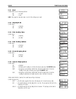
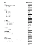
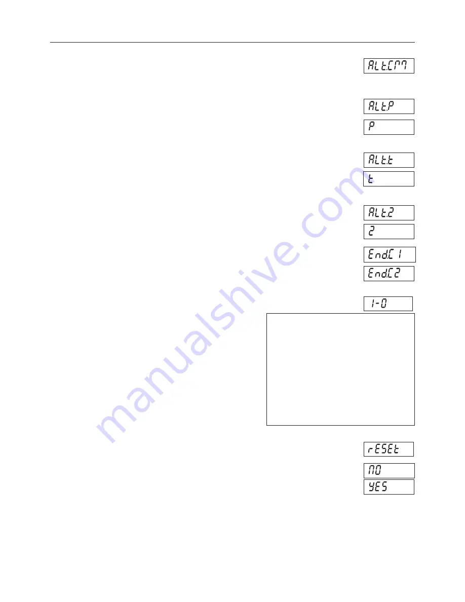
.10. Alternate Command Sub-menu

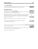
Enter ths sub-menu to set a dfferent command character for the P (Prnt), T (Tare) and Z (Zero) 
commands. 

Alternate Zero

Set the alternate command character for Zero.
         A to Z.  

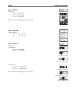
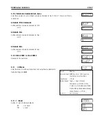
.10. End COM1 or End COM


Advance to the next menu.

Alternate Print Command

Set the alternate command character for Prnt.
         A to Z.  

Alternate Tare

Set the alternate command character for Tare.
         A to Z.  

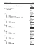
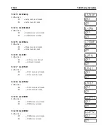
.11   I-O Menu

Enter ths menu to set the optonal nput and output devce parameters. 
Default settngs are 

bold

.

Reset         

No

, Yes

External Input 

Off

, Tare, Zero, Prnt, Functon,      

              Start-Stop, Tare-Start-Stop
Input Beep     Off, On
Relay Output   Type (-> Open, Closed), 
              Sequence (-> Normal, Hold), 
              Contact (-> Smultaneous, Break-  
              Before-Make, Make-Before-Break)
              When Stable (-> Off, On)
End.I-O        Ext I-O menu

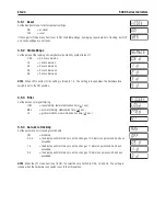
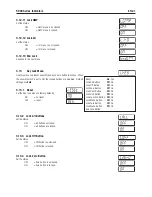
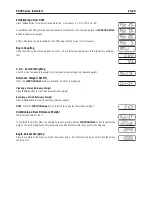
.11.1   Reset

Set the I-O menu to factory defaults
        NO       = not reset.
        YES       = reset.

Summary of Contents for T51P

Page 1: ... 5000 Series Indicators Instruction Manual T51XW Indicator T51P Indicator ...

Page 2: ...ii ...

Page 3: ... 3 2 Scale Base Without Connector to T51P or T51XW EN 12 2 3 3 RS232 Interface Cable to T51XW EN 13 2 3 4 Footswitch to T51P or T51XW EN 13 2 4 T51P Rear Housing Orientation EN 13 2 5 Mounting Bracket EN 13 3 SETTINGS EN 14 3 1 Menu Structure EN 14 3 2 Menu Navigation EN 15 3 3 Calibration Menu EN 15 3 3 1 Zero Calibration EN 16 3 3 2 Span Calibration EN 16 3 3 3 Linearity Calibration EN 17 3 3 4 ...

Page 4: ... Weighing Mode EN 26 3 6 6 Dynamic Weighing Mode EN 26 3 6 7 Check Weighing Mode EN 27 3 6 8 End Mode EN 27 3 7 Unit Menu EN 27 3 7 1 Reset EN 27 3 7 2 Kilogram Unit EN 27 3 7 3 Pound Unit EN 27 3 7 4 Gram Unit EN 28 3 7 5 Ounce Unit EN 28 3 7 6 Pound Ounce Unit EN 28 3 7 7 Tonnes Unit EN 28 3 7 8 Custom Unit EN 28 3 7 9 End Unit EN 29 3 8 GMP Menu EN 29 3 8 1 Reset EN 29 3 8 2 Date Type EN 29 3 8...

Page 5: ...nd I O EN 39 3 12 Menu Lock Menu EN 39 3 12 1 Reset EN 39 3 12 2 Lock Calibration EN 39 3 12 3 Lock Setup EN 40 3 12 4 Lock Readout EN 40 3 12 5 Lock Mode EN 40 3 12 6 Lock Unit EN 40 3 12 7 Lock Print1 EN 40 3 12 8 Lock Print2 EN 40 3 12 9 Lock COM1 EN 40 3 12 10 Lock COM2 EN 40 3 12 11 Lock GMP EN 41 3 12 12 Lock I O EN 41 3 12 13 End Lock EN 41 3 13 Key Lock Menu EN 41 3 13 1 Reset EN 41 3 13 2...

Page 6: ... 8 4 Check Weighing EN 46 4 8 5 Dynamic Weighing EN 47 5 SERIAL COMMUNICATION EN 48 5 1 Interface Commands EN 48 5 2 Output Format EN 49 5 3 Printouts EN 49 6 LEGAL FOR TRADE EN 51 6 1 Settings EN 51 6 2 Verification EN 51 6 3 Sealing EN 51 7 MAINTENANCE EN 53 7 1 Model T51P Cleaning EN 53 7 2 Model T51XW Cleaning EN 53 7 3 Troubleshooting EN 53 7 4 Service Information EN 54 8 TECHNICAL DATA EN 55...

Page 7: ...uthorized personnel The T51XW is supplied with a grounded power cable Use only with a compatible grounded power outlet For safe and dependable operation of this equipment please comply with the following safety precautions 1 1 1 Relay Option Safety Precautions This equipment may have an optional AC or DC Relay Option board installed This option allows external devices to be controlled by the Indic...

Page 8: ...3 Control Panel 4 Adjusting Knob 2 5 Mounting Bracket 6 Security Screw 7 Data Label 8 Rear Housing 9 Battery Cover 10 Screw 4 11 Power Receptacle 12 Hole plug for option 13 Strain relief for alternate load cell connection 14 Load Cell Connector 15 Hole plug for option 16 RS232 Connector TABLE 1 1 T51P PARTS 4 5 6 7 8 9 10 12 14 16 11 13 15 ...

Page 9: ... 4 7 Rear housing 8 Data Label 9 Security Screw 10 Strain relief for option 11 Strain relief for RS232 12 Strain relief for option 13 Strain relief for option 14 Strain relief for Load Cell Cable 15 Power cord TABLE 1 2 T51XW PARTS Figure 1 2 T51XW Indicator 1 2 3 4 5 6 7 8 10 11 13 14 12 15 1 2 Overview of Parts and Controls Cont 9 ...

Page 10: ...scription 1 Sense Jumper W1 2 Alternate Load Cell Terminal Block J4 3 Sense Jumper W2 4 Security Switch SW2 5 External input Terminal Block J9 6 RS232 Terminal Block J7 T51XW only 7 Load Cell Connector T51P only TABLE 1 3 MAIN PC BOARD Figure 1 3 Main PC Board 1 2 3 4 5 6 7 ...

Page 11: ...symbol 10 Pound Ounce Pound ounce symbols 11 Tonne symbol 12 Battery charge symbol 13 Custom unit symbol 14 Dynamic symbol 26 Figure 1 4 Controls and Indicators TABLE 1 4 CONTROL PANEL No Designation 15 TARE Menu button 16 Pieces symbol 17 FUNCTION Mode button 18 PRINT Units button 19 ON ZERO Off button 20 Pointer symbols not used 21 Brutto Gross symbols 22 Preset Tare Tare symbols 23 Stable weigh...

Page 12: ...orms a tare operation Secondary Function Long Press Off Turns the Indicator off Units Changes the weighing Unit Mode Allows changing the application mode Press and hold allows scrolling through modes Menu Enter the User menu Menu Function Short Press Yes Accepts the current setting on the display No Advances to the next menu or menu item Rejects the current setting on the display and advances to t...

Page 13: ...o the power receptacle Figure 1 1 item 11 then connect the AC plug to an electrical outlet 2 2 4 AC Power to T51XW Connect the AC plug to a properly grounded electrical outlet 2 2 5 Battery Power to T51P The indicator can be operated on alkaline batteries not supplied when AC power is not available It will automatically switch to battery operation if there is power failure or the power cord is rem...

Page 14: ... front housing forward Once all connections are made reattach the front housing The screws should be tightened to 2 5 N m 20 25 in lb torque to ensure a watertight seal 2 3 2 Scale Base Without Connector to T51P or T51XW Bases without a connector must be attached to the internal load cell connector on the main PC board Pass the load cell cable through the strain relief Figure 1 1 item 13 or Figure...

Page 15: ...ng Orientation The T51P is delivered in the wall mount orientation with the connections exiting below the display The rear housing may be reversed so the connections exit above the display when the T51P is placed horizontally on a bench To reverse the rear housing remove the four Phillips head screws carefully rotate the housing 180 and reinstall the screws 2 5 Mounting Bracket Attach the bracket ...

Page 16: ...UTTON BEEPER SCALE ID END SETUP DIFFERENCE DATE TIME INFO MODE NAME LAYOUT FORMAT FEED LIST END PRINT1 PRINT2 COM1 COM2 I O LOCK MENU LOCK KEY END RESET RESET RESET RESET RESET RESET STABLE ONLY 2 BAUD BAUD EXT INPUT LOCK CAL LOCK ALL AUTO PRINT PARITY PARITY INPUT BEEP LOCK SETUP LOCK OFF CONTENT STOP BIT STOP RELAY OUTPUT LOCK READOUT LOCK ZERO RESULT HANDSHAKE ADDRESS 3 TYPE LOCK MODE LOCK PRIN...

Page 17: ...yed When the button is released the Legal for Trade status is displayed followed by the first menu Press the No or Back button to move to a different menu Press the Yes button to enter the menu Once in the menu press the Yes button to view the menu item setting or press the No or Back button to move to the next menu item When viewing the setting press the Yes button to accept the setting or press ...

Page 18: ...e scale The span calibration point is established with a calibration mass placed on the scale The zero calibration point is established with no weight on the scale When SPAN is displayed press the Yes button to initiate Span Calibration The display flashes the span calibration point Place the specified weight on the scale and press the Yes button To choose a different span point or calibration uni...

Page 19: ...specified weight on the scale and press the Yes button To choose a different full point or calibration unit kg or lb edit the setting as explained in Section 3 2 Menu Navigation When the desired setting is displayed place the specified weight on the scale and press the Yes button The display shows C while the full point is established The display flashes the mid calibration point Place the specifi...

Page 20: ...N When tESt is displayed press the Yes button to initiate Calibration Test The display flashes 0 With no weight on the scale press the Yes button to record the current zero point The display shows t while the zero point is recorded The display flashes the span calibration weight using the value from the last calibration The example shows test weight of 30 kg Place the specified test weight on the ...

Page 21: ...19 43 26 17 16 16 15 15 14 14 13 13 12 12 43 26 44 32 17 17 16 16 15 15 14 14 13 13 12 44 32 45 38 18 17 17 16 16 15 15 14 14 13 13 45 38 46 45 18 18 17 17 16 16 15 15 14 14 13 46 45 47 51 19 18 18 17 17 16 16 15 15 14 14 47 51 48 58 19 19 18 18 17 17 16 16 15 15 14 48 58 50 06 20 19 19 18 18 17 17 16 16 15 15 50 06 51 13 20 20 19 19 18 18 17 17 16 16 15 51 13 52 22 21 20 20 19 19 18 18 17 17 16 1...

Page 22: ...E If the Legal for Trade menu item is set to ON the Range Capacity Graduation Zero Range Auto Tare Retain Weight Data and Legal For Trade settings are not reset 3 4 2 Range Set the number of weighing ranges SINGLE one weighing range from zero to full capacity dUAL two weighing ranges where range 1 is from zero to half capacity and range 2 is from half capacity to full capacity 3 4 3 Capacity Set t...

Page 23: ...ero up to full capacity 3 4 4 Graduation Set the scale readability 0 00001 0 00002 0 00005 0 0001 0 0002 0 0005 0 001 0 002 0 005 0 01 0 02 0 05 0 1 0 2 0 5 1 2 5 10 20 50 100 200 500 1000 NOTE Graduation settings are limited to values from Capacity divided by 1000 to Capacity divided by 30000 Therefore not all settings are available for each capacity NOTE If dUAL was selected in the rANGE menu it...

Page 24: ...e Menu settings are affected as follows Calibration functions are hidden except for Calibration Test Capacity is read only Range Graduation Power On unit Auto Tare Retain Zero Gross Indication Print Output Unit and Mode settings are locked at their current settings Zero Range is locked at 2 Stable Range is locked at 1d Auto Zero Tracking is set to 0 5d Continuous Print is disabled IP and CP RS232 ...

Page 25: ...s above the Over setting UNd OVr the beeper will sound when the weight is below the Under setting or above the Over setting 3 4 12 Button Beeper Set how the beeper sounds when a button is pressed OFF no sound ON sound 3 4 13 End Setup Advance to the next menu 3 5 Readout Menu Enter this menu to customize display functionality Default settings are bold Reset No Yes Stable Range 0 5d 1d 2d 5d Filter...

Page 26: ...ivisions per second has been exceeded NOTE When the LFT menu item is set to ON the selections are limited to 0 5d 1d and 3d The setting is locked when the hardware lock switch is set to the ON position 3 5 1 Reset Set the Readout menu to factory default settings NO not reset YES reset If the Legal for Trade menu item is set to ON the Stable Range Averaging Level Auto Zero Tracking Auto Off and Gro...

Page 27: ...ed SEt 1 powers off after 1 minute of no activity SEt 2 powers off after 2 minutes of no activity SEt 5 powers off after 5 minutes of no activity 3 5 7 Gross Indicator Set the type of gross indicator OFF disabled G GrOSS the G icon is lit when gross weights are displayed B brutto the B icon is lit when gross weights are displayed 3 5 8 End Readout Advance to the next menu 3 6 Mode Menu Enter this ...

Page 28: ...ssing the FUNCTION button AUtO averaging is automatically initiated when the load is greater than 5 divisions resetting is automatically initiated when the load is less than 5 divisions If MAN SEMI or AUtO is selected the current level setting is displayed Set the averaging time SEt 0 the first stable weight will be held on the display until it is reset display hold SEt 1 the weight readings will ...

Page 29: ...are bold 3 7 1 Reset Set the Unit menu to the factory defaults NO not reset YES reset Note If the Legal for Trade menu item is set ON the settings are not reset Reset No Yes Kilograms Off On Pounds Off On Grams Off On Ounces Off On Pounds Ounces Off On Tonnes Off On Custom Off On Factor Exponent LSD End Unit Exit UNIT menu Note Due to national laws the indicator may not include some of the units o...

Page 30: ... Custom Unit Use Custom Unit to display weight in an alternative unit of measure The custom unit is defined using a conversion factor where the conversion factor is the number of custom units per kilogram expressed in scientific notation Factor x 10 Exponent For example To display weight in troy ounces 32 15075 troy ounces per kilogram enter a Factor of 3 21508 and an Exponent of 1 Set the status ...

Page 31: ...Set the GMP menu to factory defaults NO not reset YES reset 3 8 2 Date Type Set the date format MdY Month Day Year dMY Day Month Year YMd Year Month Day Exponent Set the factor multiplier 0 100 Factor x 1 1 101 Factor x 10 2 102 Factor x 100 3 103 Factor x 1000 2 10 2 Factor 100 1 10 1 Factor 10 Least Significant Digit Set the custom unit readability 0 00001 0 00002 0 00005 0 0001 0 0002 0 0005 0 ...

Page 32: ... the time format 24 hr 24 hour format 12 hr 12 hour format 3 8 5 Time Set Set the time 24 hour format 00 to 23 hour position 00 to 59 minute position 12 hour format 12 A to 12 P hour position 00 to 59 minute position Refer to Section 3 2 Menu Navigation to enter settings current time blinking Set hours 00 to 23 Set minutes 00 to 59 current time blinking Set hours 01 to 12 A or P Set minutes 00 to ...

Page 33: ... Menu Navigation to enter settings 3 8 7 Project ID Set the Project identification 000000 to 999999 Refer to Section 3 2 Menu Navigation to enter settings 3 8 8 Scale ID Set the Scale identification 000000 to 999999 Refer to Section 3 2 Menu Navigation to enter settings 3 8 9 End GMP Advance to the next menu ...

Page 34: ...ES reset 3 9 2 Print Stable Data Only Set the print criteria OFF values are printed immediately ON values are only printed when the stability criteria are met 3 9 3 Auto Print Set the automatic printing functionality OFF disabled ON StAb printing occurs each time the stability criteria are met INtEr printing occurs at the defined interval CONt printing occurs continuously ACCEPt printing occurs ea...

Page 35: ...is printed Net Set the status OFF Disabled ON the Net weight is printed When ON StAb is selected set the condition for printing where LOAd prints when the load is stable and greater than zero LOAd Zr prints when any load is stable and equal to or greater than zero When INtEr is selected set the Print Interval 1 to 3600 seconds Tare Set the status OFF Disabled ON the Tare weight is printed Header S...

Page 36: ...d NOTE The Reference Information is dependent on the active mode Weigh mode None Count mode APW Percent mode Reference Weight Dynamic mode Level Check Weigh mode Under and Over limits Time Set the status OFF Disabled ON the Date and Time is printed Difference Set the status OFF Disabled ON the Calibration Test difference is printed Mode Set the status OFF Disabled ON the Mode is printed Name Set t...

Page 37: ... is used to define format of data output to a printer or computer Format Set the printing format MULtI a multi line single column style printout is generated A CRLF is added after each item SINGLE a single line printout is generated A TAB space is added between each item and a CLRF is used only after the very last item 3 10 COM1 and COM2 Menus The table shows the items in the communication menus D...

Page 38: ...ty 8 NONE 8 data bits no parity 3 10 4 Stop Bit Set the number of stop bits 1 1 stop bit 2 2 stop bits 3 10 5 Handshake Set the flow control method NONE no handshaking ON OFF XON XOFF software handshaking HArd hardware handshaking 3 10 6 Address Set the communication address NOTE Address is only displayed in the COM2 menu if the RS422 RS485 option is installed OFF no address 01 to 99 address 01 to...

Page 39: ...nd character for Print A to Z Alternate Tare Set the alternate command character for Tare A to Z 3 11 I O Menu Enter this menu to set the optional input and output device parameters Default settings are bold Reset No Yes External Input Off Tare Zero Print Function Start Stop Tare Start Stop Input Beep Off On Relay Output Type Open Closed Sequence Normal Hold Contact Simultaneous Break Before Make ...

Page 40: ...ternal input OFF Disabled ON Enabled 3 11 4 Relay Output Set the relay output parameters NOTE If the Relay option is not installed the OUTPUT menu and associated menu items are not available Type Set the initial state of the relay OPEN the relay output is normally open CLOSEd the relay output is normally closed CAUTION The normally closed relay condition is only active while the Indicator is power...

Page 41: ... 3 12 Menu Lock Menu Reset No Yes Lock Calibration Menu Off On Lock Setup Menu Off On Lock Readout Menu Off On Lock Mode Menu Off On Lock Unit Menu Off On Lock Print1 Menu Off On Lock Print2 Menu Off On Lock Com1 Menu Off On Lock Com2 Menu Off On Lock GMP Menu Off On Lock I O Menu Off On End Lock Menu Use this menu to prevent unauthorized changes to menu settings When the security switch is set to...

Page 42: ...locked ON Mode menu is locked 3 12 6 Lock Unit Set the status OFF Unit menu is not locked ON Unit menu is locked 3 12 7 Lock Print1 Set the status OFF Print 1 menu is not locked ON Print 1 menu is locked 3 12 8 Lock Print2 Set the status OFF Print 2 menu is not locked ON Print 2 menu is locked 3 12 9 Lock COM1 Set the status OFF COM1 menu is not locked ON COM1 menu is locked 3 12 10 Lock COM2 Set ...

Page 43: ...n Off On Lock Mode Button Off On Lock Tare Button Off On Lock Menu Button Off On End Lock Button Use this menu to prevent unauthorized access to button functions When the security switch is set to ON the locked buttons are disabled Default settings are bold 3 13 1 Reset Set the Key lock menu to factory defaults NO not reset YES reset 3 13 2 Lock All Buttons Set the status OFF all buttons unlocked ...

Page 44: ...N Tare button is locked 3 13 10 Lock Menu Button Set the status OFF Menu button is unlocked ON Menu button is locked NOTE When the Menu button is locked the user may unlock this button by holding the Menu button for 10 seconds until UNLOCK is displayed The hardware Lock Switch must be in the unlocked position 3 13 11 End Lock Advance to the next menu 3 14 Security Switch A slide switch is located ...

Page 45: ...lue empty the scale and press the TARE button The display will show the gross weight 4 4 Pre Set Tare A Pre set Tare PT is a known tare value entered using the xT command example 1 234 kg The display will show the Pre set Tare as a negative value with the PT Indicator on NOTES 1 The PT value will supersede any other Tare or PT value in memory 2 When using Pre Set Tare make sure that Auto Tare func...

Page 46: ...inter or sending the data to a computer requires that the communication parameters in the Print and Communication Menu are set refer to Sections 3 9 and 3 10 Press the PRINT Units button to send the displayed data to the communication port the Auto Print Mode in Section 3 9 function must be Off 4 8 2 Parts Counting Use this mode to count parts of uniform weight The Indicator determines the quantit...

Page 47: ...nce weight Reference Weight Ref Wt When the FUNCTION Mode button is released CLr rEF is displayed Clearing a Stored Reference Weight Press the Yes button to clear the stored reference weight Recalling a Stored Reference Weight Press the No button to recall the existing reference weight NOTE Press the FUNCTION Mode button to temporarily display the reference weight Establishing a New Reference Weig...

Page 48: ... Yes button to edit setting Settings 999950 to 999950 Refer to Menu Navigation Section 3 2 to enter settings NOTE The minus sign is used together with the first digit to show a negative value Editing the Over Setting The display shows SEt HI Press the Yes button to edit the Over setting Settings 999950 to 999950 Refer to Menu Navigation Section 3 2 to enter settings Begin Check Weighing The approp...

Page 49: ...atic or automatic mode the display must be at zero gross or net before placing the object on the scale The example is for a setting of 5 seconds During the averaging period the countdown timer decreases in one second increments NOTE If SEt 0 was selected in the Dynamic menu item the countdown timer is not displayed When the countdown has completed the readings are averaged and held on the display ...

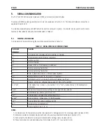
Page 50: ... button xT Enter a preset tare where x the tare value in grams PU Print current unit g kg lb oz lb oz t C custom xU Set scale to unit x 1 g 2 kg 3 lb 4 oz 5 lb oz 6 t 7 C PV Version print name software revision and LFT ON if LFT is set ON H x text Enter Header line where x line number 1 to 5 text header text up to 24 alphanumeric characters Esc R Global reset to reset all menu settings to the orig...

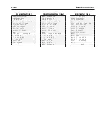
Page 51: ..._______________ Name ___________________ Name ___________________ 10 00 kg NET Quantity 100 PCS Percentage 10 11 00 kg G 11 00 kg G 11 00 kg G 10 00 kg NET 10 00 kg NET 10 00 kg NET 1 00 kg T 1 00 kg T 1 00 kg T Mode Weigh APW 0 1000 kg Ref Wt 100 00 kg Mode Count Mode Percent Each field is followed by a single delimiting space ASCII 32 Definitions Weight up to 9 characters right justified at imme...

Page 52: ...e Brook NJ 07058 USA 01 31 08 12 30 PM 01 31 08 12 30 PM Tel 1 973 377 9000 Scale ID 123456 Scale ID 123456 01 31 08 12 30 PM User ID 123456 User ID 123456 Scale ID 123456 Project ID 123456 Project ID 123456 User ID 123456 Name ___________________ Name ___________________ Project ID 123456 Final Wt 0 200 kg NET Result 10 00 kg NET OVER Name 12 34 kg G 11 00 kg G Mode Test 11 11 kg NET 10 00 kg NET...

Page 53: ... in Section 2 3 1 6 Set the position of the security switch SW2 to ON as shown in Figure 1 3 item 4 7 Close the housing 8 Reconnect power and turn the indicator on NOTE When Legal for Trade is set to ON and the security switch is set to ON the following menu settings cannot be changed Zero Calibration Span Calibration Linearity Calibration GEO Range Capacity Graduation Power On Unit Zero Range Aut...

Page 54: ... Seal When the scale base is attached to the indicator using a connector it is necessary to seal the load cell cable to the indicator in some jurisdictions The load cell sealing collar P N 80500737 Figure 6 5 is available as an accessory Figure 6 5 Load Cell Sealing Collar 3 3 3 ...

Page 55: ...o the Scale or will not zero when turned on Load on Scale exceeds allowable limits Load on Scale is not stable Load Cell damage Remove load on Scale Wait for load to become stable Service required Unable to calibrate Lock Calibration Menu set to On LFT menu set to On Incorrect value for calibration mass Set Lock Calibration Menu to Off Refer to Section 3 12 Menu Lock Set LFT menu to Off Use correc...

Page 56: ...6 1 Set the security switch to the ON position REF WT Err Reference Weight too small The weight on the platform is too small to define a valid reference weight Use a greater weight for sample 7 4 Service Information If the troubleshooting section does not resolve your problem contact an authorized Ohaus Service Agent For Service assistance in the United States call toll free 1 800 526 0659 between...

Page 57: ...nes custom Functions Static Weighing Dynamic Weighing Counting Checkweighing Percent Weighing Display 25 mm 1 in High 6 digit 7 segment LCD Over Accept Under Indicators Red Green Yellow LED Backlight White LED Keypad 4 button membrane switch Ingress Protection IP66 Load Cell Excitation Voltage 5V DC Load Cell Drive Up to 8 x 350 ohm Load Cells Load Cell Input Sensitivity Up to 3 mV V Stabilization...

Page 58: ...it 80500727 Rechargeable Battery Kit 80500729 RS422 485 Interface Kit 80500731 RS232 Interface kit 80500733 TABLE 8 3 ACCESSORIES The Rechargeable Battery Kit RS232 Kit RS422 485 Kit AC Relay Kit DC Relay kit and Foot switch must be installed by a qualified technician DESCRIPTION PART NUMBER Foot Switch 71173378 Interface Cable PC 25 pin T51P 80500524 Interface Cable PC 9 pin T51P 80500525 Interfa...

Page 59: ...EN 57 5000 Series Indicators 8 3 Drawings and Dimensions Figure 8 1 T51P Indicator Overall Dimensions with Mounting Bracket Figure 8 2 T51XW Indicator Overall Dimensions with Mounting Bracket ...

Page 60: ...hen the equipment is operated in a commercial environment This equipment generates uses and can radiate radio frequency energy and if not installed and used in accordance with the instruction manual may cause harmful interference to radio communications Operation of this equipment in a residential area is likely to cause harmful interference in which case the user will be required to correct the i...

Page 61: ...ument must strictly observe the re verification period and inform the respective W M authorities Disposal In conformance with the European Directive 2002 96 EC on Waste Electrical and Electronic Equipment WEEE this device may not be disposed of in domestic waste This also applies to countries outside the EU per their specific requirements The Batteries Directive 2006 66 EC introduces new requireme...

Page 62: ...ed by accident or misuse exposed to radioactive or corrosive materials has foreign material penetrating to the inside of the product or as a result of service or modification by other than Ohaus In lieu of a properly returned warranty registration card the warranty period shall begin on the date of shipment to the authorized dealer No other express or implied warranty is given by Ohaus Corporation...

Page 63: ......

Page 64: ...Ohaus Corporation 19A Chapin Road P O Box 2033 Pine Brook NJ 07058 USA Tel 973 377 9000 Fax 973 593 0359 www ohaus com P N 80251400 C 2010 Ohaus Corporation all rights reserved Printed in China 80251400 ...

Reviews: