CHAPTER 2 DIAGNOSTIC GUIDE
Ohaus Corporation www.ohaus.com
2-2
Valor
™ 2000/4000 Series Service Manual
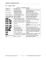
2.2.2 Checking Load Cells for Trouble
1.
Perform a Resistance Test
, to determine if the Load Cell is severely damaged or a
short circuit to the frame has occurred.
Note:
The Load Cell must be completely disconnected from the Printed Circuit Board
and at no load when the resistance readings are taken.
Using an ohm meter, measure and record resistance between each pair of wires
from the Load Cell, as specified in Table 2-1. Compare the measured readings with
the specified values in Table 2-1.
If the resistance readings are in the range specified, skip to the next section. If they
are outside the expected range, open circuit or short-circuit across any two wires, the
Load Cell is defective: replace it. (See Chapter 3.)
TABLE 2-1. LOAD CELL RESISTANCE READINGS (in Ohms)
Model
Ex+ to Ex
–
S+ to S
–
Ex+ to S
–
Ex+ to S+
Ex
–
to S+
Ex
–
to S
–
All models
404 ± 10
350 ± 4
289 ± 10
289 ± 10
289 ± 10
289 ± 10
2.
Perform an Output Voltage Test
:
Measure the no load, 50% load and full load
output.
The reading should meet the Load Cell specifications. The Load Cell output
should be very close to linear over its capacity range.
NOTE
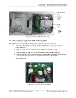
: The following steps involve power applied to the scale. Load Cell solder
contacts can be used as measuring points. See Figure 2-1.
The EXE+ and EXE
– wires should be connected to the PCB, and the SIG+ and SIG–
wires must be disconnected. Record the colors for each wire connection before
disconnecting. (See Table 2-2 for typical color code for Valor 7000.)
TABLE 2-2. COLOR CODE FOR LOAD CELL WIRING
*
EXE
–
EXE+
SIG+
SIG
–
AMI
BLACK
GREEN
WHITE
RED
ZEMIC
BLACK
RED
GREEN
WHITE
*
Color codes may vary.
– Insert the Platform Support into the Load Cell Frame, place the Platform on top,
and turn on power to the scale.
– Using a voltmeter, measure and record the excitation voltage supplied to the
PCB: with no load on the Platform, measure the voltage across points 4 and 1 of
Load Cell connection on the PCB (+EXE and
–EXE). This voltage must be
approximately 4.6~4.7 Volts dc with the Load cell connected. If the voltage is
lower, disconnect the Load Cell cable from the PCB and measure again. If the
voltage is not 4.6~4.7 Volts dc, the Load Cell is defective and must be replaced.
If the voltage remains low, the PCB is defective and must be replaced.
Summary of Contents for VALOR 4000
Page 3: ......


