background image

CHAPTER 5  PARTS LISTS & DIAGRAMS 


Valor

 7000 Series Service Manual 

5-3 

Ohaus Corporation  www.ohaus.com 


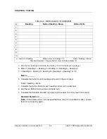
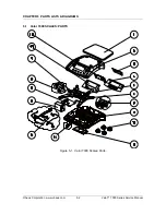
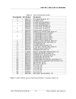
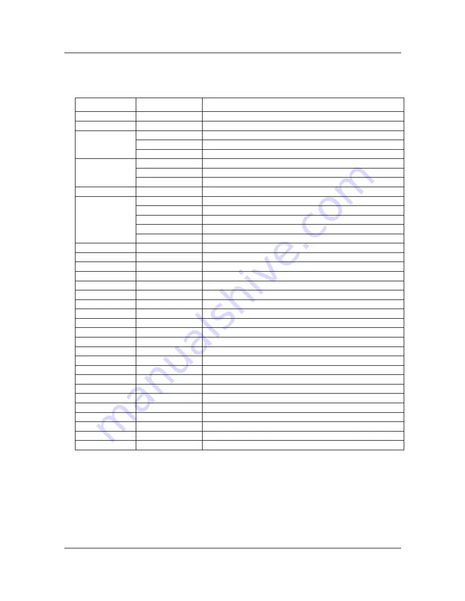
TABLE 5-1.  Valor 7000 SCALES: PARTS 

Drawing Item  Part Number 

Description 

1


30037417


Pan,Plastic,R31,RC31,V71


2


30037395


Housing,Top,V71


3


30025998


Function Label,Rear,EN,V71


30060923


Function Label,Rear,JP,V71


30037467


Function Label,Rear,KR,V71


4


30025997


Function Label, Front,EN,V71


30060922


Function Label, Front,JP,V71


30037466


Function Label, Front,KR,V71


5


30037434


Spider,Upper, R31,R21,RC31,RC21,V71


6


30037401


LoadCell AMI C3 3kg,V71P1502T


30037402


LoadCell AMI C3 5kg ,V71P3T


30037403


LoadCell AMI C3 11kg ,V71P6T


30037404


LoadCell AMI C3 22kg ,V71P15T


30037405


LoadCell AMI C3 40kg,V71P30T


7


30037435


Spider,Down, R31,R21,RC31,RC21,V71


8


30037420


Hardware Kit,R31,R21,RC31,RC21,V71


9


30037400


Housing,Bottom,V71


10


30037421


Feet,R31,R21,RC31,RC21,V71


11


30037422


Cover,Option, R31,R21,RC31,RC21,V71


12


30037392


Switch Power, R31,RC31,V71


13


30037428


PCBA,Main,R31,RC31,V71


14


71168359


Battery,Lead Acid,R31,R21,RC31,RC21,V71


15


30037419


Harness,R31,R21,RC31,RC21,V71


16


30037438


PCBA,IR sensor with a IR cover,V71P


17


30037430


PCBA,Display,LCD,R31,R21,V71 


18


30037433


PCBA,Display,LCD,rear,V71 


NA


30037383


Packaging Box carton,R31,R21,RC31,RC21,V71


NA


30037384


Packaging Box,complete,R31,R21,RC31,RC21,V71


NA


30037457


Manual, Instr.,JP,V71


NA


30060919


Manual, Instr.,KR,V71


NA


72200232


Line Cord , US


NA


72200229


Line Cord, EU


NA


72200228


Line Cord, AU


NA


72200231


Line Cord, GB


NA


72200230


Line Cord, JP


NA


30031898


Manual,CD, EN ES FR DE IT, V71


Note

:  For parts numbers, see your local Ohaus distributor, or visit www.ohaus.com. 


Summary of Contents for Valor 7000 series

Page 1: ...SERVICE MANUAL VALOR 7000 Ohaus Corporation 7 Campus Drive Suite 310 Parsippany NJ 07054 973 377 9000...

Page 2: ...publication but Ohaus Corporation assumes no liability arising from the use or misuse of this material Reproduction of this material is strictly prohibited Material in this manual is subject to chang...

Page 3: ...3 Testing the Printed Circuit Board PCB 2 4 2 2 4 Diagnostic Guide 2 6 CHAPTER 3 MAINTENANCE PROCEDURES 3 1 Preventive Maintenance 3 1 3 1 1 Preventive Maintenance Checklist 3 1 3 2 Service Strategy...

Page 4: ...ucture 1 5 2 1 Load Cell Resistance Readings in Ohms 2 2 2 2 Color Code for Load Cell Wiring 2 2 2 3 Load Cell Output Readings in mV with 3 3V Excitation 2 3 2 4 Diagnostic Guide 2 6 3 1 Mounting Bolt...

Page 5: ...ponents Appendix A Standard Calibration Explains procedures for Standard Calibration performed prior to using a scale and after service Appendix B Service Calibration Describes the Service Menu and su...

Page 6: ...0 1 30000 LFT ON Resolution nMax 1 3000 1 3000 1 3000 1 3000 1 3000 Linearity 2d r0 0001 kg r0 0002 kg r0 0005 kg r0 001 kg r0 002 kg Repeatability 2d r0 0001 kg r0 0002 kg r0 0005 kg r0 001 kg r0 002...

Page 7: ...g Press Toggles through active weighing units Short Press in Menu Toggles through available settings Function Mode Back Short Press Selects function setting Long Press Selects active Mode Short Press...

Page 8: ...item 11 in figure 3 2 will remain lit The scale can be operated during charging and the battery is protected against overcharging For maximum operating time the battery should be charged at room tempe...

Page 9: ...O M L O C k E n d Menu Items Reset kg g lb oz lb oz End Reset Stable A Print Contnt Layout Data Tr End Reset Baud Parity Stop Handsh Alt Cm End L Cal L Setup L Read L Mode L Unit L Print L COM End 1 5...

Page 10: ...is not accessible Zero Range is locked at 2 Stable Range setting is locked at 1d Auto Zero Tracking setting is locked at 0 5d Units are locked at their current settings Filter is locked at current se...

Page 11: ...CHAPTER 1 GETTING STARTED Valor 7000 Series Service Manual 1 7 Ohaus Corporation www ohaus com Figure 1 3 Sealing...

Page 12: ...ith the most common cause first If the first remedy does not fix the problem proceed to the next remedy Before attempting to repair the balance read all chapters of this manual to be familiar with the...

Page 13: ...d full load output The reading should meet the Load Cell specifications The Load Cell output should be very close to linear over its capacity range NOTE The following steps involve power applied to th...

Page 14: ...ts at Zero Load 50 and full scale capacities See Table 2 3 for typical readings Figure 2 1 Top view of main PCB NOTE Table 2 3 indicates typical readings Actual values can vary but should remain linea...

Page 15: ...n 3 Using a DVM measure the excitation voltage EXE and EXE in Figure 2 1 The reading should be 3 1 volts dc This is the excitation voltage for the Load Cell and is regulated If the voltage is lower re...

Page 16: ...ue 6 Adjust the Simulator to simulate 0 load 50 load and 100 load for the capacity that the scale is rated for See Table 2 3 for values to use If the resulting readings are unstable the Main PC Board...

Page 17: ...below Power On Zero limit Err 8 3 Over Range Error Weight reading exceeds Overload limit Err 8 4 Under Range Error Weight reading below Underload limit Err 8 5 Tare out of range Adjust tare value to b...

Page 18: ...tronics to stabilize 3 1 1 Preventive Maintenance Checklist The scale should be inspected and checked regularly as follows 1 Remove the Pan and Sub Pan to inspect and clean the area beneath the Pan 2...

Page 19: ...the eight screws holding the Housing in place See Figure 3 1 3 Move the top housing a little bit backward and then raise and remove the top housing 4 Separate Top Housing from Bottom Housing Avoid str...

Page 20: ...PCB to the bottom housing 3 If either the Main PCB or the Load Cell is to be replaced note the order of the wire colors and then disconnect the Load Cell Cable from the Main PCB See Figure 3 2 4 Posit...

Page 21: ...washers that hold the Load Cell assembly frame and load cell to the Bottom Housing Remove the bolts and their washer pairs that hold the Load Cell Frame to the Load Cell Use a high leverage Allen wren...

Page 22: ...ual to the scale s capacity See Table 3 2 There are four Overload Stop Bolts See Figure 3 5 Adjust the Overload Stops per Table 3 2 1 Adjust the Overload Stop Bolt so that the gap between the Load Cel...

Page 23: ...VERLOAD STOP GAP SETTINGS Model Max Capacity Overload Stop Gap V7000 Scale Load Cell A B mm C D mm V71P1501T 1 5kg 3kg 0 6 0 5 V71P3T 3kg 5kg 0 8 0 7 V71P6T 6kg 10kg 1 5 1 1 V71P15T 15kg 20kg 2 4 1 7...

Page 24: ...2 Pull the quick connect tabs free of the battery posts and lift out the battery Figure 3 7 Rechargeable battery 3 Position the replacement battery in the compartment on an angle sufficient to access...

Page 25: ...S REQUIRED The masses required to test the Ohaus Valor 7000 scales must meet the requirements of ASTM Class 4 or OIML F2 Tolerance The mass values are listed in Table 4 1 TABLE 4 1 TEST MASS VALUES Mo...

Page 26: ...ication for each model listed in Table 1 1 1 Power on the balance The reading on the display should be 0g 2 Select a mass weighing near the maximum capacity of the balance and place it on the center o...

Page 27: ...test set up the instrument as follows Set Up Follow the steps in Appendix A Section A 2 Setup and Calibration Record Settings Zero Tracking Setting ____________ Displayed Units ____________ Mass Used...

Page 28: ...ge 6 Mean Reading 1 Reading 2 Reading 3 Reading 4 Reading 5 7 Reading 6 Reading 7 Reading 8 Reading 9 Reading 10 10 Mean ________ 6 Calculate the Delta for each reading and record in the work sheet De...

Page 29: ...press ON Zero Off 3 Place the test mass on the Scale record the weight and remove 4 Place Load 2 on the Scale and press ON Zero Off 5 Place the test mass on the Scale record the weight and remove 6 P...

Page 30: ...test weight in the center of the Weighing Pan 2 Tare the balance 3 Move the weight to point A and record the reading 4 Move the weight to point B and record the reading 5 Move the weight to point C an...

Page 31: ...d NOTE In all cases where a part is replaced the scale must be thoroughly checked after the replacement is made The scale MUST meet the parameters of all applicable specifications in this manual If fu...

Page 32: ...CHAPTER 5 PARTS LISTS DIAGRAMS Ohaus Corporation www ohaus com 5 2 Valor 7000 Series Service Manual 5 1 Valor 7000 SCALES PARTS Figure 5 1 Valor 7000 Scales Parts...

Page 33: ...der Down R31 R21 RC31 RC21 V71 8 30037420 Hardware Kit R31 R21 RC31 RC21 V71 9 30037400 Housing Bottom V71 10 30037421 Feet R31 R21 RC31 RC21 V71 11 30037422 Cover Option R31 R21 RC31 RC21 V71 12 3003...

Page 34: ...libration process 2 Allow the scale to warm up for approximately five minutes after stabilizing to room temperature 3 To abort calibration press Exit key or turn the scale off anytime during the calib...

Page 35: ...accept SpaN will then be shown Press Yes to begin the span calibration 0 kg will be displayed SpaN 0 3 Press Yes to accept C will be displayed while zero reading is stored Next the display shows the c...

Page 36: ...factory Linearity and Span calibrations no pre set limits Note Be careful not to touch the scale or the surface it rests on while calibration is in progress as it will cause the process to fail B 1 S...

Page 37: ...e Service Span Calibration menu Set the graduation of the scale 0 00005 0 02 Grad B 5 Service Span Calibration When SPAN appears press YES to accept the Service Span Calibration menu or No to advance...

Page 38: ...to indicate the calibration unit The example shows the mid calibration point value for a Scale Capacity of 3 kg Place the specified calibration weight on the pan and press Yes C flashes while the mid...

Page 39: ...o the Expand menu item Note Ramp is used to troubleshoot load cell problems 0 represents no signal from the A D 100 reflects the upper signal range of the A D ramMp 0 0 to 100 0 B 8 Expand Menu When e...

Reviews: