5/Maintaining the Servo-controlled Humidifier
5-2 5-2
Troubleshooting humidifier problems
Symptom
Possible cause(s)
Recommended action(s)
Controller does not come on
Power is off or the power
Connect the power cord
is disconnected
All indicators go out while the Open fuse
Discontinue use and call
unit is in use
service
Auto Shutoff/
Fill tray is not properly
Push tray all the way in
Add Water indicator on
installed
Unit is low on water
Be sure water is at proper
level
Humidity switches
Enable indicator not on
Press enable switch again
(
?
and
M
), or Enable
switch, do not respond.
Controller failure
Discontinue use and call
service
Humidity level will not
Tray overfill
Check water level.
Remove rise to set point
some water if too high
Door/portholes open
Close door/portholes
Operator prompt cannot be
Controller failure.
Discontinue use and call
silenced and all indicators
for service
are off.
System failure
Electrical failure
Note the readings on the
RH display and set RH
displays. Discontinue
use and call service
E1.1 error code displayed
Add Water has
Fill humidifier tray with
on power up
not re-set
water. Allow heater to cool
for 2 minutes. Restart. If
problem persist, call service
Audible prompt cannot
Short time drop out
Turn humidifier off for at
be silenced and display
in line voltage
least 2 seconds and back
shows random characters
on, if problem persists
call service
Recording error codes
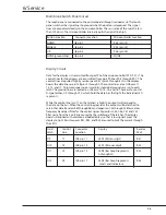
In the event of a system failure, a continuous prompt tone will sound and the system
failure indicator will light. Before shutting off the unit and removing it from service,
make note of any error code that appears. The first two characters of the code will
appear in the % Relative Humidity display. The third and final character appears
on the Set RH bar graph display; 1 = the first segment from the bottom, 2 = the
second segment, and so forth. The error code will aid qualified service personnel
in diagnosing problems. For more information see Error codes in section 6 of this
manual.
Summary of Contents for Ohio Care Plus
Page 20: ...2 General Information 2 4 2 4 Notes...
Page 24: ...4 Using the Servo controlled Humidifier 4 2 4 1 Notes...
Page 46: ...6 Service 6 18 6 18...
Page 53: ...8 Schematics 8 1 Figure 8 1 Wiring Diagram Servo controlled Humidifier 8 Schematics CI 18 059...
Page 55: ...8 Schematics 8 3 Figure 8 3 Digital section of the Control Display Board Assembly CI 18 061...
Page 56: ...8 Schematics 8 4 Figure 8 4 Analog section of the Control Display Board Assembly CI 18 062...
Page 58: ...8 Schematics 8 6 Figure 8 6 Display section of the Control Display Board Assembly CI 18 064...
Page 67: ......


