background image

– 

13 

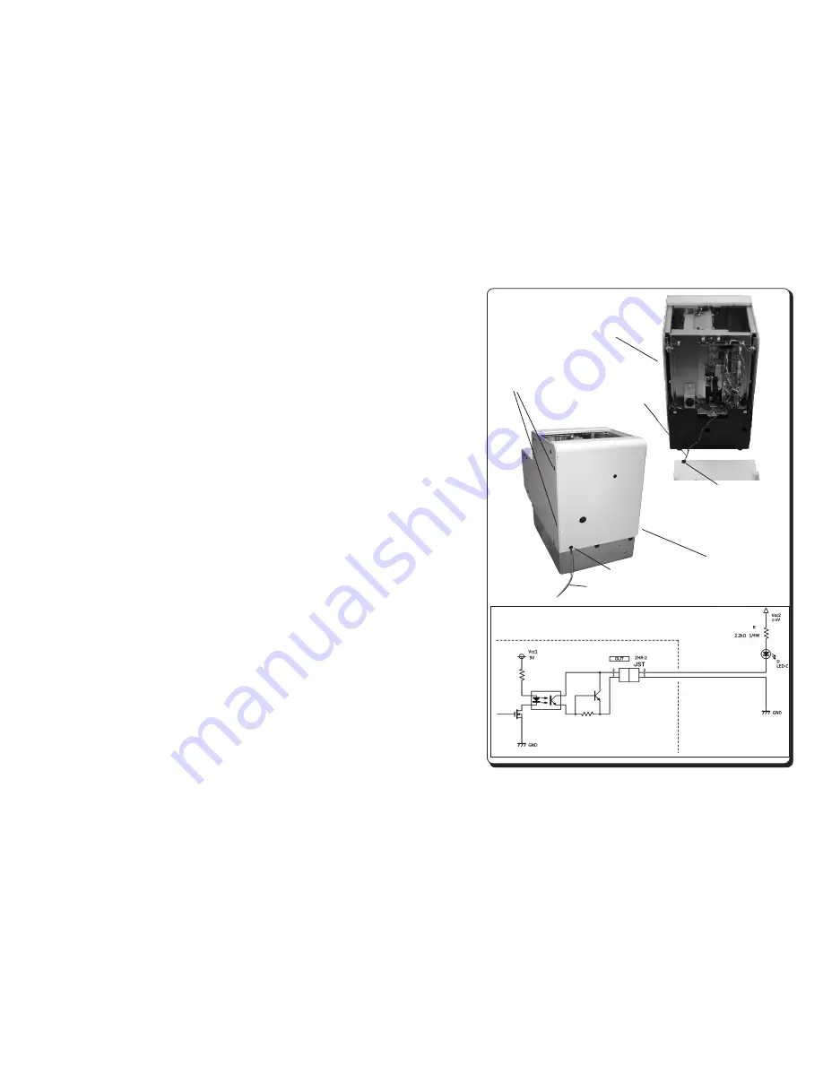
Signal 

line

Cover rear

Grommet

Signal line

Grommet

Give one or more turns to the signal 

line around the coaching clip so it 

can be safely pulled from outside.

Mounting screw 

(M2.6)

Total four screws, 

including screws on 

the opposite side

machine board

External

Purple

Gray

5.8  External Output Signal Line

This machine has an external output signal line, allowing for external 

generation of a signal synchronized with the timing at which the LCD panel 

LED lights up, as an open collector output.  Use this output to connect an 

indicator, buzzer or the like externally.

The signal line is housed inside this machine.  To use the signal line, lead 

it outside through the grommet in the rear of the cover.

㼀㼔㼕㼟㻌㼟㼕㼓㼚㼍㼘㻌㼣㼕㼞㼑㻌㼟㼔㼍㼘㼘㻌㼎㼑㻌㼡㼟㼑㼐㻌㼣㼕㼠㼔㻌㼍㼡㼠㼛㼙㼍㼠㼕㼏㻌㼍㼟㼟㼑㼙㼎㼘㼥㻌㼙㼍㼏㼔㼕㼚㼑㼟
㼛㼞㻌㼑㼤㼠㼑㼞㼚㼍㼘㻌㼟㼏㼞㼑㼣㻌㼏㼛㼡㼚㼠㼑㼞㼟㻚
㼇㻲㼡㼚㼏㼠㼕㼛㼚㼉㻦
㻌㻌㻿㼏㼞㼑㼣㻌㼜㼞㼑㼟㼑㼚㼠㻌㻌㻌㻌㻌㻌㻌㻌㻌㻌㻌㻌㻌㻌㻦㻌㼟㼕㼓㼚㼍㼘㻌㼔㼕㼓㼔㻌㻔㻻㻺㻕
㻌㻌㻵㼚㼏㼛㼙㼕㼚㼓㻌㼏㼡㼞㼞㼑㼚㼠㻌㻌㻌㻌㻌㻌㻌㻌㻌㻌㻌㻦㻌㼟㼔㼍㼘㼘㻌㼎㼑㻌㼘㼕㼙㼕㼠㼑㼐㻌㼠㼛㻌㼘㼑㼟㼟㻌㼠㼔㼍㼚㻌㻝㻜㻜㼙㻭
㻌㻌㻌㻖㻯㻭㼁㼀㻵㻻㻺㻦㻌㻭㼐㼐㼕㼠㼕㼛㼚㼍㼘㻌㼞㼑㼟㼕㼟㼠㼛㼞㻌㼕㼟㻌㼞㼑㼝㼡㼕㼞㼑㼐㻌㼛㼚
㻌㻌㻌㻌㻌㻌㻌㻌㻌㻌㻌㻌㻌㻌㻌㻌㻌㻌㻌㻌㻌㻌㻌㻌㻌㼑㼤㼠㼑㼞㼚㼍㼘㻌㼏㼕㼞㼏㼡㼕㼠㻌㼒㼛㼞㻌㼞㼑㼓㼡㼘㼍㼠㼕㼚㼓㻌㼏㼡㼞㼞㼑㼚㼠㻌㻖
㼇㻯㼍㼜㼍㼏㼕㼠㼥㼉㻦
㻌㻌㻹㼍㼤㻌㻰㻯㻌㼏㼡㼞㼞㼑㼚㼠㻌㻌㻌㻌㻌㻌㻌㻌㻌㻌㻌㻦㻌㻝㻜㻜㼙㻭
㻌㻌㻱㼤㼠㼑㼞㼚㼍㼘㻌㼟㼡㼜㼜㼘㼥㻌㼢㼛㼘㼠㼍㼓㼑㻌㻦㻌㻡㻌㼠㼛㻌㻞㻠㼂㻰㻯㻌㻌㻔㻹㼍㼤㻦㻌㻞㻣㼂㻰㻯㻕
㼇㻯㼍㼡㼠㼕㼛㼚㼉㻦
㻌㻌㻼㼘㼑㼍㼟㼑㻌㼗㼑㼑㼜㻌㼠㼔㼑㻌㼘㼑㼚㼓㼠㼔㻌㼛㼒㻌㼛㼡㼠㼜㼡㼠㻌㼟㼕㼓㼚㼍㼘㻌㼣㼕㼞㼑㻌㼘㼑㼟㼟㻌㼠㼔㼍㼚㻌㻟㼙㻧
㻖㻌㼀㼔㼑㻌㼜㼡㼞㼜㼘㼑㻌㼣㼕㼞㼑㻌㼒㼡㼚㼏㼠㼕㼛㼚㼟㻌㼍㼟㻌㼟㼕㼓㼚㼍㼘㻌㼛㼡㼠㼜㼡㼠㻌㼔㼕㼓㼔㻌㻔㻯㼛㼘㼘㼑㼏㼠㼛㼞㻌㼑㼚㼐㻕㻘
㻌㻌㼣㼕㼠㼔㻌㼠㼔㼑㻌㼓㼞㼍㼥㻌㼣㼕㼞㼑㻌㼍㼟㻌㼏㼛㼙㼙㼛㼚㻌㻔㻱㼙㼕㼠㼠㼑㼞㻌㼑㼚㼐㻕

エスケーパネジ取出し部にネジが


有るか


無いか


の信号を取出せます。

ネジ締めロボット、 汎用カウンター等との接続にご利用ください。


[

仕様

]  

ネジ検出時


ON


吸込み電流


max 100mA

以下になるように


固定抵抗等で電流制限をかけてください。


[

定格

直流電流


max 100mA


外部印加電圧


5 ~

24VDC

(max

 27VDC)


[

注意

信号線の長さは

3m

以内としてください。


C

側 (信号線紫色) を高電位、


E

側 (信号線灰色) を低電位にしてご使用ください。

紫色の線ーーー>信号線


(ネジが無いとき

OFF)


(ネジがあるとき ON)

灰色の線ーーー>コモン線

CN10

接続例

Example

Inside

Outside

Purple

Gray

High voltage

Low voltage

When LED is lighting

Summary of Contents for FM-36 Series

Page 1: ...manual Maintenance FM 36 Series Automatic Screw Feeder FM1MA01M a R e a d t h e s e i n s t r u c t i o n s f o r t h e p r o p e r u s e o f t h i s m a c h i n e A f t e r h a v i n g r e a d t h e...

Page 2: ...screw feeding or cause the machine to be overloaded and malfunction Please refer to the diagram below and carefully adjust the screw level to be 2 3mm below upper edge of the rail When the scoop plate...

Page 3: ...periods of time CAUTION CAUTION CAUTION 1 Before Use Thank you very much for purchasing our Automatic Screw Feeder FM 36 series Please check up the accessories supplied with it before using it Accesso...

Page 4: ...eration turn off the power switch and disconnect the AC adapter from the power outlet If you continue to use this machine while it is acting abnormally a risk of fire electric shock or personal injury...

Page 5: ...machine Unload screws from the unloading port and move all screws from the rail to the screw bin take them from the chamber See the illustrations below for ejecting screws Use maximum care in ejectin...

Page 6: ...bin lid Bit guide assembly Rail assembly Escaper disc Front cover Shutter installed in front of the passage plate Bin scooping plate Brush Timer setting control DC jack Bin scooping plate Screw bin P...

Page 7: ...hips factory adjusted to handle pan head screws If this machine requires adjustment to meet the kind of screw to use make the following checks and adjustments beforehand Brush check and adjustment Pas...

Page 8: ...eing put in the screw bin Actuation of the overload protection circuit If the moving parts of this machine are overloaded the drive motor reverses for a predetermined period of time and then returns t...

Page 9: ...te check and adjustment Rail assembly and Escaper Unit check and adjustment When the power switch is turned on the Bin scooping plate moves up and down for a predetermined period of time and then stop...

Page 10: ...the total of preset counts of screws Increments each time a preset count of screws are accumulated at the unloading port Each time the count of screws has accumulated at the unloading port this machi...

Page 11: ...igit in the preset count indicator blinking Press the PRE SET button once momentarily while the digit is blinking to change that digit If you do not press the PRE SET button while the digit is blinkin...

Page 12: ...level as shown at right Check that the tip of the brush swipes above the head of the applied screws placed in the rail groove The alignment and transfer of screws would be adversely affected if the b...

Page 13: ...nt is complete verify correct operations Screws on the rail are delivered smoothly Screws do not fall out from the rail 2 Adjustments for a clearance between Escaper disk and Extended part of Holding...

Page 14: ...a certain count of screws has accumulated at the unloading port This delay can be adjusted with the timer A Timer setting control screw is found in the rear of this machine as shown at right Turn the...

Page 15: ...has an external output signal line allowing for external generation of a signal synchronized with the timing at which the LCD panel LED lights up as an open collector output Use this output to connect...

Page 16: ...r cleaning Before detaching the rail from this machine turn off the power switch and remove the screws from the Screw bin to prevent screws from falling into the machine Remove two front cover mountin...

Page 17: ...the plastic part of the brush won t hit the passage plate when the brush assembly operates A ideally clearance of 0 is recommended For adjustment instructions see 5 4 Brush Check and Adjustment 7 2 R...

Page 18: ...emoval procedure The Escaper Unit requires positional adjustments in relation to the rail groove See the instructions below 7 4 Replacing the Rail Assembly Turn off the power switch before performing...

Page 19: ...een loaded or screws of different nominal diameters were present The supply of screws in the Screw bin has used up Check that AC adapter power connection Manipulate the unloading lever to unload screw...

Page 20: ...late Putting an appropriate supply of screws in the Screw bin could fix the problem Remove unusual screws and then adjust the passage plate Remove the screws in an unusual posture Follow the instructi...

Page 21: ...nominal diameter of the rail have been loaded Dust and oil have stuck on the rail The rail is not vibrating due to screws stuck in rail gaps for example Exhausted motor Poorly adjusted passage plate...

Page 22: ...the unloading port The unloading lever has not been pressed firmly Adjust the Holding plate position Adjust the groove position of the rail and the escaper disc Turn the power switch off then back on...

Page 23: ...e passage plate is too high The holding plate is too high The distance between the rail end and the escaper disc is too far Moving parts are undergreased Adjust the Timer setting control screw Remove...

Page 24: ...t to change without prior notice for the sake of improvement Exclusive adapter Switching type Dimension Weight Screw capacity A preset count Accessories x1 AC x1 x1 x1 x1 Input AC100 240V 50 60Hz Outp...

Page 25: ...3640 4 0 FR40SET FR40 F40 W3640 FM 3650 5 0 FR50SET FR50 F50 W3650 FM 3660 6 0 FR60SET FR60 F60 W3660 FM 36 Replacement parts Rail Assembly Main motor With Harness NJ09782 10 Drive motor Assembly NJ0...

Page 26: ...plemented at a reasonable charge without regard to the warranty period Defects caused by misuse Defects caused by product modifications or unauthorized repairs Defects caused by natural disasters or A...

Page 27: ...B B JI 9 9 PP 0 0 0 0 0 11 External dimension Timer setting control DC jack Product seal s 9 9 PP VV 0 0 0 0 0 5 5 5 5 5 VV D E unit mm...

Page 28: ...any part of this user s manual without permission is strictly prohibited by copyright law Copyright OHTAKE ROOT KOGYO CO LTD 27 021 0902 Tel 0191 24 3144 Fax 0191 24 3145 27 Kangasaki Hagisyou Ichino...

Reviews: