– 14 –
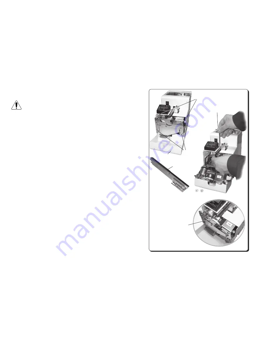
Front cover
Remove two front cover mounting screws,
including one on the opposite side
Loosen the Rail front-rear position
lock screw and pull out the rail.
Clean the rail groove
Escaper Unit
mounting screws
Escaper Unit
Adjust the positions of the rail
groove and the escaper disc
groove.
In the photo, the Holding plate
is removed, but adjustments
may also be carried out
with the Holding plate being
moved upward.
6. Maintenance
Turn off the power switch before performing check and
adjustment work.
Eject all applied screws from within this machine before
proceeding with maintenance work.
A dirty rail groove could slow down the applied screw transfer speed. If the
rail groove is found noticeably soiled, wipe it off with a thin cloth moistened
with alcohol.
If the rail groove is difficult to clean, the rail can be detached from this
machine for cleaning. Before detaching the rail from this machine, turn off
the power switch and remove the screws from the Screw bin (to prevent
screws from falling into the machine).
Remove two front cover mounting screws and move the front cover.
Remove the Escaper Unit mounting screw and then detach the escaper
disc.
(See 7.3, “Replacing the Escaper Unit.”
Then, loosen the Rail front-rear position lock screw and pull out the rail
assembly to front.
The rail should require replacement if its rail groove is soiled or damaged
to impair its function.
If the rail assembly has been removed from this machine, it is necessary to
make positional adjustments with the tip of the rail and the escaper disc.
• Align the groove rail and the groove in the escaper disc with each other.
• Mount the Escaper Unit to keep the top surface of the groove in the
escaper disc lower than the top surface of the rail groove.
• Turn on this machine and then make adjustments with the longitudinal
position of the rail so its tip will not hit the escaper disc when the rail
vibrates.
CAUTION


