background image

3 Heating circuits

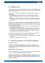
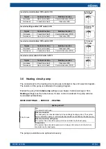
3.1 Buffer tank

Enable the buffer tank from 

Initial Setup

 settings (see chapter 

Commissioning

) or from

Heating

 settings (Device settings → Service → Heating, see the table below).

→ HEATING

Heating circuits take the heating energy either directly from the heat pump’s condenser or the heating

circuit’s buffer tank. The 

Heating buffer sensor

 setting determines which method is used. Each circuit’s

equipment is selected under the relevant circuit.

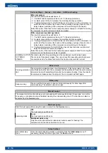
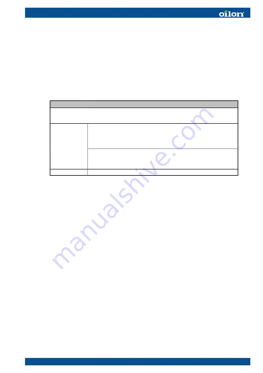
Not connected

The heat pump is connected directly to the building’s heating system without a

buffer tank. No buffer tank sensor is connected. The configuration may include an

(unpowered) instantaneous water cylinder, but not a buffer tank regulated by the

heat pump.

Heating buffer

sensor

Connected

The heat pump is connected to a buffer tank which is regulated by the heat pump.

The tank is equipped with a temperature sensor which is connected to the heat

pump. Any heating circuits in the system are connected to the buffer tank.

Buffer

Buffer tank temperature.

You can enable the buffer tank only if buffer tank temperature measurement is enabled.

The temperature sensor used for this is the buffer tank sensor (TE255). See the

instructions for installing the sensor in section 

Buffer tank sensor

.

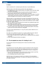
3.2 Buffer tank sensor

The heat pump comes with the buffer tank temperature sensor (TE255) already

connected.

Connections

If the heating circuit has no buffer tank, disconnect the sensor from the relevant

terminal block.

If required, you can use the same terminals for connecting the unit’s built-in heating

water return sensor (T201; condenser in). See the necessary connections in the unit’s

electric diagram.

You’ll find the ends of the sensor cable’s wires on the unit’s switchboard near the

terminal block for sensors.

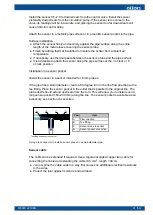
If you wish to enable both the buffer tank sensor (TE255) and the heating water return

sensor (TE201), install an auxiliary controller and connect the return sensor (TE201) to

the auxiliary controller. Select the terminals for the sensor from the auxiliary controller’s

settings. The auxiliary controller will be delivered with additional instructions.

M8003 2219EN

19 (54)

Summary of Contents for ECO Inverter+ 7

Page 1: ...M8003 2219EN 24 May 2022 INSTALLATION AND COMMISSIONING ECO Inverter 7 25 ...

Page 2: ......

Page 3: ...7 3 Heating circuits 3 1 Buffer tank 19 3 2 Buffer tank sensor 19 3 3 Flow temperature sensor for heating circuit 1 20 3 4 Heating water temperature return to condenser 22 3 5 Heating circuit s control valve 22 3 6 Heating circuit pump 25 3 7 Heating circuits 2 and 3 27 4 Commissioning 4 1 General 28 4 2 Signing in as a service level user 28 4 3 Initial setup settings 29 4 4 Design outdoor tempera...

Page 4: ...6 7 EU Product Data 52 2 54 M8003 2219EN ...

Page 5: ...initial setup M8005 34793601 EasyAce User manual M8004 34793603 1 3 Safety notice and warnings Read these instructions carefully before installation commissioning operation or maintenance of the device The given instructions must be followed Throughout this manual the following symbols are used to point out very important information Use special caution The DANGER symbol indicates an immediate haz...

Page 6: ...components Refrigerant Refrigerant leaking from an open or broken circuit may cause asphyxiation severe frost damage arrhythmia or neurological symptoms If you suspect a refrigerant leak leave the area immediately and seek fresh air Help and warn others The unit includes a hermetically sealed refrigerant circuit filled with refrigerant R 410A Refrigerant R 410A is a mixture of two refrigerants HFC...

Page 7: ...k or work under the heat pump or any other suspended load Wireless touch screen Use the wireless touch screen provided with the unit only for operating the heat pump Using the touch screen for any other purpose may cause slowdowns or interference in the use of the unit s automation system or prevent the system from being used altogether Other considerations To avoid slipping keep floor surfaces dr...

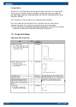
Page 8: ...st three hours before starting the compressor 1 5 Scope of delivery Equipment and components Item PCS Oilon designation Wireless touch screen For using the EasyAce control app to control the heat pump s automation system 1 378810400 Wireless touch screen ver 1 Outdoor temperature sensor Sensor ID is TE0 Connect the sensor to the cable TE0 W1 1 36217543 Outdoor temperature sensor ver 1 Condenser pu...

Page 9: ...IRCUIT 3 TE232 Heating circuit 3 flow temperature OA P231 Heating circuit 3 pump OA FV232 Heating circuit 3 control valve OA TE233 Room temperature 3 OA REFRIGERANT CIRCUIT COMP1 Compressor S TE2 Hot gas temperature S PS1 Low pressure switch S PS2 High pressure switch S DATA HUB HUB Connection device for the EasyAce system EasyAce Hub S If an auxiliary controller is not installed one heating circu...

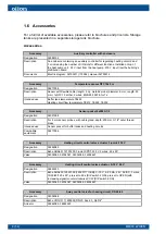
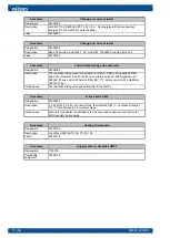
Page 10: ...perature TE255 Heating circuit flow temperature TE212 TE222 TE232 Accessory Sensor pocket 6x200 G1 2 Designation 34021268 Description For 6 mm sensor probes with cable gland depth 200 mm G1 2 outer thread brass Intended use Sensor pocket for buffer tanks and heating circuits Compatible equipment 36217266 Accessory Heating circuit control valve actuator 3 point 230 V Designation 36962089 Descriptio...

Page 11: ... Actuator 36962089 36962220 Accessory 3 way control valve for heating circuit DN40 25 Designation 1154332 Description Esbe VRG131 11603400 DN40 Kvs 25 Rp 1 1 2 Actuator 36962089 36962220 Accessory Change over valve kit 1 Designation GEOEXCV1 Description Includes a change over valve and valve actuator designation 34034063 and 34034064 Accessory Change over valve kit 2 Designation GEOEXCV2 Descripti...

Page 12: ...hut off and non return valve LK 508 AquaNode 22 090025 fill valve LK 536 ThermoFill EA EN 1717 safety valve LK 514 MultiSafe 090116 10 bar Intended use Thermostatic mixing valve assembly with fill connection Accessory In line heater 6 kW Designation 37069089 Description 3 x 2 kW 230 V L N connection box thermostat 25 85 C overheat protection 110 C manual reset 28 mm steel pipes Intended use Electr...

Page 13: ...e unit securely in a vertical position onto its own leveling feet Level the machine using the machine s leveling feet Maintenance and access clearance The system must include shut off valves that allow the unit to be isolated from the brine circuit heating circuit and the domestic water system The unit should be easy to access for servicing from all sides For ease of access leave a sufficient clea...

Page 14: ... In from the bottom out from the top WI Heating water in condenser in 1 1 4 outer thread WO Heating water out condenser out 1 1 4 outer thread BI brine circuit in evaporator in 1 1 4 outer thread BO brine circuit out evaporator out 1 1 4 outer thread AF Leveling feet M10 DIN ISO 17 16 mm TC Switchboard cover Torx T25 The unit s fuses and some of its terminal blocks are located under this cover FC ...

Page 15: ...revd ECO Inverter ver 1 Heat pump L1 L2 L3 H1 H2 H3 H4 B1 B2 ECO Inverter 7 25 525 407 83 674 659 598 122 590 33 Heat pump BI BO Ø WI WO LF BF Ø DF ECO Inverter 7 25 ISO 228 1 G1 1 4 B ISO228 1 G 1 1 4 B 425 522 35 M8003 2219EN 13 54 ...

Page 16: ...80 120 Wire cross sectional area mm 2 0 50 0 75 1 0 1 5 Outdoor installation Install the sensor outside the building with the sensor cable gland pointing downwards Place the sensor in a position where the prevailing outdoor temperature can be measured as accurately as possible Make sure that the sensor is not exposed to solar radiation or heat from the building Even though the sensor housing is pr...

Page 17: ...instructions When an in line heater has not been installed and enabled in the automation system the standard position for fuse F2 is OFF If an in line heater has been installed and it needs to be disabled disable the heater from the heat pump s settings If an in line heater has been installed and enabled in the settings do not set the heater s fuse to the OFF position unless there is a fault in th...

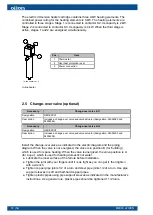
Page 18: ...2 Designation GEOEXCV2 Description Includes a change over valve and valve actuator designation 34034205 and 34034204 Install the change over valve as indicated in the electric diagram and the piping diagram When the valve is not energized the valve is in position B for building which is used for space heating When the valve is energized the valve position is A for aqua which is used for heating do...

Page 19: ... possible If necessary use thermal paste between the sensor probe and the pocket walls To ensure that the sensor probe remains firmly seated at the bottom of the sensor pocket secure the sensor cable with a cable gland The cable can be extended if required Use a regular insulated copper twin cable for connecting the cable and extending the cable 0 5 mm 2 length 40 m Join or splice the cable ends i...

Page 20: ...e gland plate on the switchboard cover ensuring that the glands are properly sealed Ensure that no leaks or condensate can travel along cables or through or along insulation onto the switchboard behind the panel 18 54 M8003 2219EN ...

Page 21: ...d to the buffer tank Buffer Buffer tank temperature You can enable the buffer tank only if buffer tank temperature measurement is enabled The temperature sensor used for this is the buffer tank sensor TE255 See the instructions for installing the sensor in section Buffer tank sensor 3 2 Buffer tank sensor The heat pump comes with the buffer tank temperature sensor TE255 already connected Connectio...

Page 22: ... and the pocket walls To ensure that the sensor probe remains firmly seated at the bottom of the sensor pocket secure the sensor cable with a cable gland The sensor cable is approximately 4 5 m long The sensor probe s diameter is 6 mm and length 50 mm The cable can be extended if required Use a regular insulated copper twin cable for connecting the cable and extending the cable 0 5 mm 2 length 40 ...

Page 23: ... in a sensor pocket Iinstall the sensor in a pocket intended for 6 mm probes If the pipe has a small diameter create a 90 degree turn in the line flow direction with a tee fitting Place the sensor pocket in the outlet that is parallel to the original line The probe itself should extend upstream from the turn This will allow you to install even a long sensor pocket 150 200 mm along the line The sen...

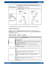
Page 24: ...s an optional accessory 3 5 Heating circuit s control valve The heat pump can control both 230 V 3 point control valves and 0 10 V 24 V control valves See the instructions for connecting the control valve actuator to the heat pump in the unit s electric diagram The control outputs for both valve types are enabled by default and are simultaneously active so there is no need to activate them The pos...

Page 25: ...The heat pump is connected directly to the building s heating system The system has no circulation pump or control valve that would be controlled by the heat pump Direct connection with pump The system has a circulation pump which is controlled by the heat pump Circuit in use 3 way valve The system has a circulation pump and a 3 way control valve both of which are controlled by the heat pump Off 0...

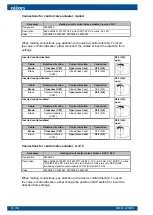
Page 26: ...3 Q8 X2 3 Q8 open Inverted control enabled Cable Rotation direction Control direction Connection Brown Clockwise CW Open more heat X2 4 Q9 Black Counterclockwise CCW Closed less heat X2 3 Q8 X2 4 Q9 open Inverted control enabled Cable Rotation direction Control direction Connection Brown Clockwise CW Closed less heat X2 3 Q8 Black Counterclockwise CCW Open more heat X2 4 Q9 X2 4 Q9 open Connection...

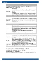
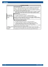
Page 27: ...e CCW 0 V open 10 V closed 3 6 Heating circuit pump The connections for the heating circuit pump are indicated in the unit s electric diagram The location of the pump is indicated in the piping diagram Enable the pump from Initial setup settings see chapter Commissioning or from Heating settings see the table below If valve control is enabled the pump will also be enabled automatically DEVICE SETT...

Page 28: ...ning and set the pump speed to a level that allows the flow rate in each circuit to be adjusted to a suitable level After this return the valves to their normal position In radiator heating systems remove any thermostats and set the pump speed to a level that allows the flow in each radiator to be adjusted to a suitable level Once the adjustment is complete reinstall the thermostats Constant press...

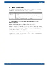
Page 29: ...4793611 110992 manual 34793612 The auxiliary controller is supplied with an electric diagram and the necessary installation instructions Install the auxiliary controller and its enclosure on top of the top cover Heating circuits 2 and 3 operate in the same way as heating circuit 1 and the available settings are identical Once the auxiliary controller has been installed and circuits 2 and 3 have be...

Page 30: ...ioning process Once the process is complete hand the wireless touch screen over to the end customer 1 Switch on the wireless touch screen by pressing the power button 2 Start the EasyAce app Start the commissioning process by signing in to the service level This will give you access to the necessary settings 4 2 Signing in as a service level user To gain access to all settings sign in as a service...

Page 31: ... setup The Initial setup settings menu contains the basic settings required during the commissioning process Go through the settings during installation Once the settings are complete hide the Initial setup menu by tapping the option at the bottom of the screen You can choose to display this menu again anytime from the Service menu by tapping Initial setup Device settings Service Initial setup Dev...

Page 32: ...tion pump which is controlled by the heat pump Circuit in use 3 way valve The system has a circulation pump and a 3 way control valve both of which are controlled by the heat pump Min flow temperature The system will keep the flow temperature determined by the heating curve above this temperature value Usually the minimum flow temperature should be set at or slightly above the required room temper...

Page 33: ...tpoint the delay will be reset Power increase delay The electric heater s power increase delay after the first power stage has been activated Once the delay has elapsed the next electric heater power stage will be switched on Increase the delay if you wish to move forward the point at which the next power stages will be switched on to provide supplementary heating in parallel with the compressor a...

Page 34: ...ver heating domestic hot water Select this option if the fuse for the heat pump power supply is not rated for running the compressor and the electric heater in parallel Mode for heating operating mode selection for space heating With compressor parallel operation The electric heater will be switched on if 1 The outdoor temperature is below 5 C freezing protection 2 An alarm prevents the compressor...

Page 35: ...lapses for a third time Decrease the delay if you wish to have the power stages switch off earlier after the flow water temperature exceeds its setpoint If the delay is greater than 0 the heater power stages will remain switched on even after the flow water temperature has exceeded the setpoint Setting the delay slightly above zero will usually result in a more stable flow water temperature Usuall...

Page 36: ...STAGES The rated output for the power stages in the condenser circuit s in line heater There can be three power stages The value is used for assessing electrical power consumption and in functions that restrict the heat pump s electrical current Brine circuit Freezing protection limit The minimum permissible brine circuit temperature If the temperature in the brine circuit falls below this limit t...

Page 37: ...oteknillinen yhdistys r y Helsinki Finland National Building Code of Finland part D5 1985 2007 part D3 2012 Ympäristöministeriön asetus uuden rakennuksen energiatehokkuudesta Finlex 1010 2017 Test reference year 2012 for building energy demand and impacts of climate change Finnish meteorological institute reports 2011 6 Sitra Reports 53 Weather data for building physical studies and the building e...

Page 38: ...k and the heat pump If the heating system includes a buffer tank each heating circuit has its own pump Another case where a heating circuit has its own pump is when the system has no buffer tank but the heating circuit includes a 3 way valve for regulating the circuit s temperature In configurations with a buffer tank the brine pump will run only when the tank is being heated The unit s automation...

Page 39: ...perature Domestic hot water tank heating will start when the DHW tank temperature minus the switching difference falls below the domestic hot water target temperature Domestic hot water heating will stop when the DHW tank has been heated up or the maximum DHW heating time has elapsed If the heating time elapses the system will resume DHW heating after the minimum time for space heating has elapsed...

Page 40: ... additional equipment such as heating circuit pumps into consideration ECO Inverter MODEL RATED CAPACITY kW 3 400 V 50 Hz PE 7 25 Dimensions and weight Width mm 525 Depth mm 590 Height mm 674 Empty weight kg 136 In line heater In line heater as standard no Can be equipped with an in line heater 6 kW yes Pipe connections Condenser and evaporator connection ISO 228 thread G 1 1 4 Maximum permissible...

Page 41: ...Minimum permissible temperature C 15 Low pressure switch Low pressure cutoff setpoint bar g 3 4 0 5 Pressure reset setpoint bar g 5 9 0 5 High pressure switch High pressure cutoff setpoint bar g 45 1 2 Pressure reset setpoint bar g 34 2 0 Compressor Compressor type Scroll 6 3 Performance data To view performance data in other conditions please use the Oilon Selection Tool www oilon com The heat pu...

Page 42: ...5 55 65 2 3 2 3 Cooling capacity kW Water in C Water out C Min 50 Hz 90 Hz Max B0 3 W20 25 20 25 5 1 8 7 15 6 20 6 B0 3 W30 35 30 35 4 6 7 9 14 1 18 7 B0 3 W40 45 40 45 4 2 7 0 12 6 16 7 B0 3 W47 55 47 55 3 7 6 1 10 9 14 6 B0 3 W55 65 55 65 5 1 9 1 Electrical power kW Water in C Water out C Min 50 Hz 90 Hz Max B0 3 W20 25 20 25 1 0 1 7 3 4 5 0 B0 3 W30 35 30 35 1 3 2 1 4 1 6 0 B0 3 W40 45 40 45 1 ...

Page 43: ...9 2962 4030 4 18 991 3 B0 3 W47 55 47 55 607 979 1764 2407 4 18 987 6 B0 3 W55 65 55 65 753 1333 4 18 983 2 Evaporator flow rate m 3 h Water in C Water out C Min 50 Hz 90 Hz Max cp kJ kg K ρ kg m 3 B0 3 W20 25 20 25 1 50 2 56 4 58 6 05 4 21 968 1 B0 3 W30 35 30 35 1 37 2 32 4 16 5 50 4 21 968 1 B0 3 W40 45 40 45 1 22 2 07 3 70 4 91 4 21 968 1 B0 3 W47 55 47 55 1 07 1 80 3 22 4 29 4 21 968 1 B0 3 W...

Page 44: ...5 55 65 2 2 2 2 Cooling capacity kW Water in C Water out C Min 50 Hz 90 Hz Max B0 4 W20 25 20 25 4 9 8 4 15 0 19 8 B0 4 W30 35 30 35 4 5 7 6 13 6 18 0 B0 4 W40 45 40 45 4 0 6 8 12 1 16 0 B0 4 W47 55 47 55 3 5 5 9 10 5 14 0 B0 4 W55 65 55 65 4 9 8 7 Electrical power kW Water in C Water out C Min 50 Hz 90 Hz Max B0 4 W20 25 20 25 1 0 1 7 3 3 5 0 B0 4 W30 35 30 35 1 3 2 1 4 1 6 0 B0 4 W40 45 40 45 1 ...

Page 45: ...83 2877 3914 4 18 991 3 B0 4 W47 55 47 55 591 953 1716 2341 4 18 987 6 B0 4 W55 65 55 65 735 1299 4 18 983 2 Evaporator flow rate m 3 h Water in C Water out C Min 50 Hz 90 Hz Max cp kJ kg K ρ kg m 3 B0 4 W20 25 20 25 1 08 1 85 3 31 4 37 4 21 968 3 B0 4 W30 35 30 35 0 99 1 68 3 00 3 97 4 21 968 3 B0 4 W40 45 40 45 0 88 1 49 2 67 3 54 4 21 968 3 B0 4 W47 55 47 55 0 78 1 30 2 32 3 09 4 21 968 3 B0 4 ...

Page 46: ...5 55 65 2 5 2 5 Cooling capacity kW Water in C Water out C Min 50 Hz 90 Hz Max B5 2 W20 25 20 25 6 1 10 4 18 7 24 8 B5 2 W30 35 30 35 5 6 9 5 17 0 22 5 B5 2 W40 45 40 45 5 0 8 4 15 1 20 1 B5 2 W47 55 47 55 4 4 7 4 13 2 17 7 B5 2 W55 65 55 65 6 1 11 0 Electrical power kW Water in C Water out C Min 50 Hz 90 Hz Max B5 2 W20 25 20 25 1 0 1 6 3 4 5 2 B5 2 W30 35 30 35 1 3 2 1 4 1 6 2 B5 2 W40 45 40 45 ...

Page 47: ...5 30 35 1 64 2 79 5 00 6 63 4 22 966 4 B5 2 W40 45 40 45 1 47 2 48 4 46 5 93 4 22 966 4 B5 2 W47 55 47 55 1 29 2 17 3 89 5 20 4 22 966 4 B5 2 W55 65 55 65 1 81 3 25 4 22 966 4 Evaporator flow rate kg h Water in C Water out C Min 50 Hz 90 Hz Max cp kJ kg K ρ kg m 3 B5 2 W20 25 20 25 1743 2964 5316 7041 4 22 966 4 B5 2 W30 35 30 35 1588 2693 4834 6411 4 22 966 4 B5 2 W40 45 40 45 1420 2398 4307 5727...

Page 48: ...ature 35 C 212 206 212 Average temperature application max flow water temperature 55 C 153 152 160 Seasonal space heating energy efficiency class 2 Low temperature application max flow water temperature 35 C A A A Average temperature application max flow water temperature 55 C A A A Seasonal DHW heating energy efficiency ηs 1 2 Load profile XL 116 116 116 Energy efficiency class in DHW heating ηs ...

Page 49: ...6 4 Technical data sheet EN 14825 Technical data sheet ECO Inverter 7 25 ECO Inverter 7 25 datasheet ver 1 M8003 2219EN 47 54 ...

Page 50: ...st output temperature 68 C compressor speed and heating capacity are kept at approximately 75 of the unit s maximum speed and power Minimum value Maximum value ECO Inverter 7 25 absolute recommended absolute recommended Brine into the evaporator C 6 5 25 5 Brine out of the evaporator C 10 9 Temperature difference across the evaporator circuit C 1 5 4 Water into the condenser C 15 20 63 61 Water fr...

Page 51: ...nser circuit pump Oilon designation Pump Description 34023129 Grundfos UPMXL GEO 25 125 180 PWM 1 phase wet motor G 1 1 2 outer thread installation dimension 180 mm inverse PWM 3 180 W 0 04 1 42 A The bold ascending curve in the diagram indicates the unit s condenser circuit pressure drop as a function of flow rate The remaining portion of the pump s total head can be used for circulating a heatin...

Page 52: ...h 1 phase wet motor G 1 1 2 outer thread installation dimension 180 mm manual control and 0 10 V 16 310 W 0 16 1 37 A motor protection 1 6 2 5 The bold ascending curve in the diagram indicates the device s evaporator circuit pressure drop as a function of flow rate The remaining portion of the pump s total head can be used for circulating the brine circuit The fluid in the graph is a mixture of wa...

Page 53: ...e Brine into the evaporator C 0 0 Brine out of the evaporator C 4 3 Water into the condenser C 30 30 Water from the condenser C 35 35 Temperature difference across the evaporator circuit C 4 3 Temperature difference across the condenser circuit C 5 5 Maximum cooling capacity kW 18 0 18 7 Maximum heating capacity kW 23 7 24 4 Evaporator circuit flow m 3 h 3 97 5 50 Evaporator circuit flow kg h 3846...

Page 54: ... kWh 11519 g sound power level LWA dB A 45 h specific precautions that shall be taken when the space heater is assembled installed or maintained 1 STANDARD RATING CONDITIONS BRINE 0 3 C WATER 47 55 C COLDER AND WARMER CLIMATE CONDITIONS j total rated heat output of heat pump and supplementary heater under colder climate conditions Prated Psup kW 22 4 j total rated heat output of heat pump and supp...

Page 55: ...t temperature outdoor temperature TOL C DECLARED COEFFICIENT OF PERFORMANCE FOR PARTIAL LOAD AT AN INDOOR TEMPERATURE OF 20 C AND THE OUTDOOR TEMPERATURES AND FLOW TEMPERATURES GIVEN BELOW BRINE 0 3 C 7 C COPd 3 00 2 C COPd 3 98 7 C COPd 4 61 12 C COPd 5 28 bivalent temperature Tbiv C 10 C operating limit temperature TOL C POWER CONSUMPTION When the unit is in OFF mode POFF kW 0 002 when the therm...

Page 56: ...t can cause a serious injury The weight of the unit presents a crush hazard Disassembly recycling and or disposal at end of life Recover the refrigerant and the compressor oil transfer for recycling or disposal as required by applicable laws rules and regulations The other components should also be recycled and disposed of in compliance with applicable laws rules and regulations The values present...

Page 57: ......
Page 58: ...Asentajantie 15 FI 67600 KOKKOLA FINLAND Niittytie 25 A FI 01300 VANTAA FINLAND Tel 358 0 207 281 868 Fax 358 0 207 281 867 Email info oilon com Contact information of Oilon dealer Date of installation ...

Reviews: