3 Installation
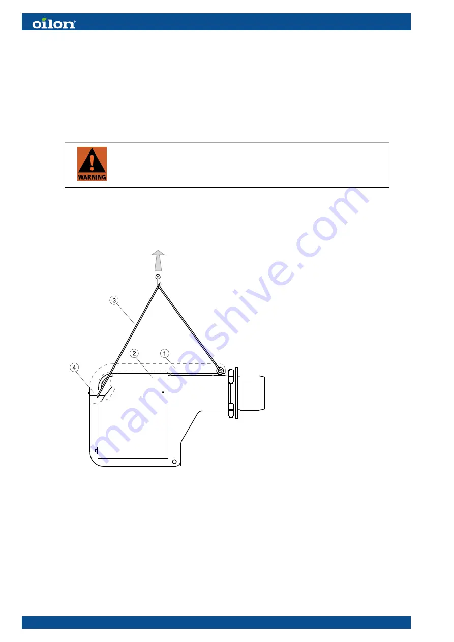
3.1 Lifting the burner
● The unit may be lifted only by qualified personnel with a good
understanding of the regulations and safety instructions for lifting.
● Always use all indicated lifting points of the particular lifting direction.
● Do not go under the burner or any other suspended load.
The burners are attached and supported to a transportation base. The base can be
lifted from all sides with a forklift. When lifting the package, the center of gravity must
be in the middle between the forks to avoid falling.
B444K ver. 3
1
Protective cover
2
Protective cover
3
Lifting strap
4
Lifting support
1. Take off protective covers (1 and 2).
2. Place the lifting strap (3) to the lifting eyes and around the lifting support (4).
3. Lift the burner as shown in the drawing.
3.2 Space requirements
Leave enough space on each side of the burner for installation, commissioning,
and maintenance purposes. The minimum space requirements are presented in the
following.
18 (111)
M4219 2305EN
Summary of Contents for GP-600 M
Page 2: ......
Page 16: ...Block diagram of contact links Block diagram ver 7 14 111 M4219 2305EN...
Page 87: ...5 5 Time sequence diagram gas use 7550f57e 0515 Gp1 ver 6 M4219 2305EN 85 111...
Page 113: ...M4219 2305EN 111 111...
Page 114: ...112 111 M4219 2305EN...
Page 115: ......


