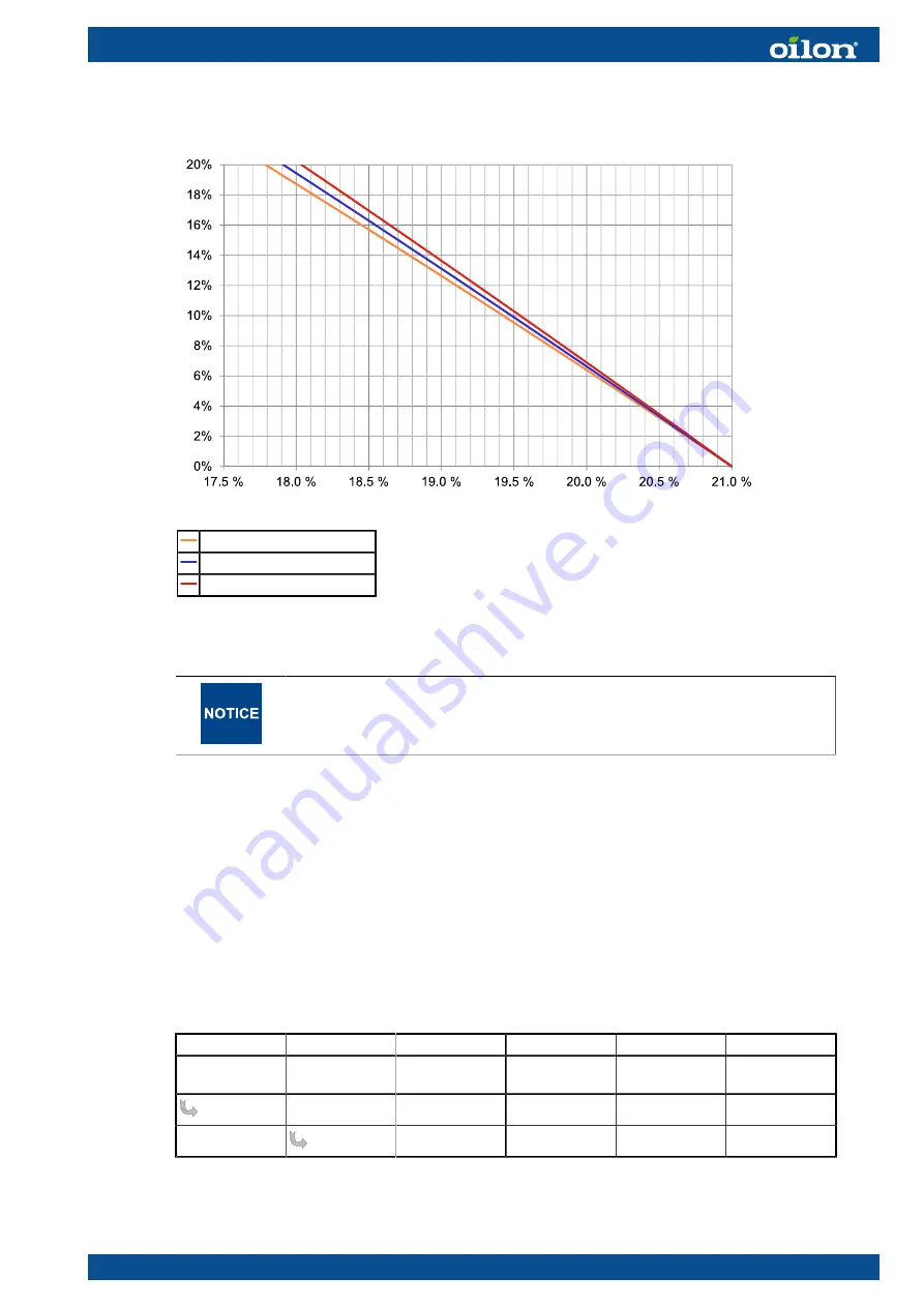
Natural gas combustion, flue gas recirculation (%)
FGR natural gas ver. 2
Flue gas O2 = 2%
Flue gas O2 = 3%
Flue gas O2 = 4%
Y axis: FGR, %, X axis: Mixture O2 content (dry), %.
FGR may cause unstable combustion. To avoid noise, vibration or
other disturbance, the settings must always be defined for each burner
separately.
4.19 Capacity range
Burner capacity range can be set as required at service level. The minimum capacity
can be greater than the first curve point, and the maximum capacity can be below the
last curve point. During start-up, the burner runs from ignition capacity to minimum
capacity and continues to normal operation. Ignition capacity can be greater, smaller, or
equal to the first curve point capacity.
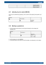
In the menu, set the minimum and maximum capacity individually for each fuel:
Description
Params. &
Display
RatioControl
GasSettings
M4219 2305EN
61 (111)
Summary of Contents for GP-600 M
Page 2: ......
Page 16: ...Block diagram of contact links Block diagram ver 7 14 111 M4219 2305EN...
Page 87: ...5 5 Time sequence diagram gas use 7550f57e 0515 Gp1 ver 6 M4219 2305EN 85 111...
Page 113: ...M4219 2305EN 111 111...
Page 114: ...112 111 M4219 2305EN...
Page 115: ......


