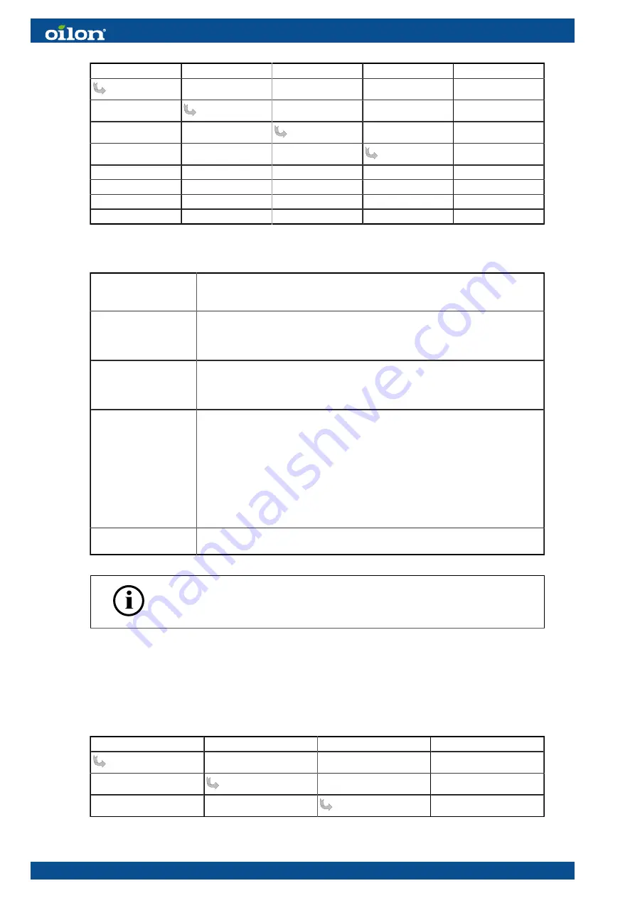
Params. & Display
O2Contr/Guard
FuelSettings
OptgMode
auto deact
man deact
O2 Limiter
O2 Control
conAutoDeac
O2 trim control operating modes
man deact
Use this setting when creating O2 ratio curve.
Both
O2Limiter
and
O2Control
are deactivated. Burner operates according to
parameterized ratio curves.
O2 Limiter
Only
O2Limiter
is active. Oxygen sensor must have reached its operating
temperature. If not, start-up will be prevented. If oxygen sensor or O2 module
causes a failure during burner operation, burner stops, tries to restart or lockout
occurs.
O2 Control
Both
O2Limiter
and
O2Control
are active. Oxygen sensor must have reached its
operating temperature. If not, start-up will be prevented. If oxygen sensor or O2
module causes a failure during burner operation, burner stops, tries to restart or
lockout occurs.
conAutoDeac
Use this setting during normal operation.
Both
O2Limiter
and
O2Control
are active. Burner starts, though oxygen sensor
has not reached its operating temperature. Burner operates along parameterized
ratio curves. When oxygen sensor has reached its operating temperature and
sensor test has been successfully completed, both
O2Limiter
and
O2Control
are
active. If oxygen sensor or O2 module cause failure during burner operation,
both
O2Limiter
and
O2Control
are deactivated. Burner operates along
parameterized ratio curves. O2 trim control status in operating and display unit
is automatically set to
auto deact
, and error code is displayed. Error code is
maintained until O2 trim control is manually deactivated or activated.
auto deact
O2 trim control has automatically been deactivated and burner operates along
parameterized ratio curves.
Do not select this option!
If O2 trim has been automatically deactivated, then you can reactivate it
from:
Operation
→
O2Ctrl Activate
→
Activate
→.
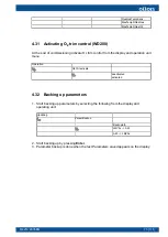
4.23 O
2
trim control load limitation (WD200)
Select
O2CtrlThreshold
from the operating and display unit menu as follows:
Params. & Display
O2Contr/Guard
Fuel settings
O2CtrlThreshold
66 (111)
M4219 2305EN
Summary of Contents for GP-600 M
Page 2: ......
Page 16: ...Block diagram of contact links Block diagram ver 7 14 111 M4219 2305EN...
Page 87: ...5 5 Time sequence diagram gas use 7550f57e 0515 Gp1 ver 6 M4219 2305EN 85 111...
Page 113: ...M4219 2305EN 111 111...
Page 114: ...112 111 M4219 2305EN...
Page 115: ......


