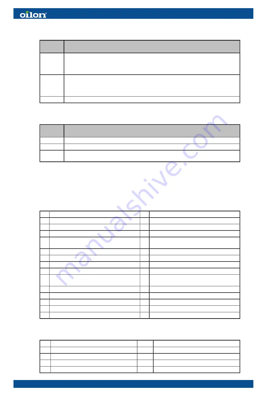
Control switch
Switch
position
State
0 - STOP Burner start-up by control devices is prevented. If the switch is turned to the ‘0’ position while
the burner is running, a controlled shutdown is initiated. The green indicator light on the
switch indicates that the control voltage for burner automation (burner control, servomotors)
is switched on.
1 - RUN When a start signal is received from a control device, the burner starts. The burner control
start-up program begins. The burner operates controlled by the capacity controller or at a
manually preset load. Burner control supervises burner operation and performs a controlled
shutdown or, if necessary, a safety shutdown and lockout.
R - RESET Burner failures are reset.
Signal lamps
Signal
lamp
State
H8
Gas flame: the light is on when the main gas valves are open.
H10
Boiler failure: the light is on when the boiler safety loop is open and lockout is active.
H30
Burner failure: the light is on when a failure has occurred in burner operation and lockout is
active.
5.3 Legend to time sequence diagrams
Phases:
00 Lockout phase
50 2nd safety time
01 Safety phase
52 Interval 2 (ti2)
10 Homerun
54 Low-fire position
12 Standby (stationary)
60 Operation 1 (stationary)
21 Shutoff valve ON (start release)
62 Operation 2
Low-fire position
22 Fan motor ON
70 Post-combustion time
24 Pre-purge position
72 Post-purge position
30 Pre-purge time (tv1)
74 Post-purge time (tn1)
32 Pre-purge time (tv)
76 Flue gas recirculation post-purge position
34 Pre-purge time (tv2) (flue gas recirculation
ARF)
78 Post-purge time (tn3)
36 Ignition position
79 Direct start
38 Pre-ignition (Z) ON
80 Valve proving evacuating time
40 Burner valve ON
81 Valve proving time atmospheric pressure
42 Ignition OFF
82 Valve proving filling time
44 Interval 1 (ti1)
83 Valve proving time gas pressure
Times:
t0
Post-purge lockout position
t78
Post-purge time 3 gas / oil (tn3)
t01 Max. time safety phase
t80
Valve proving evacuate time
t10 Min. time home run
t81
Valve proving time atmospheric pressure
t21 Min. time start release
t82
Valve proving filling time
t22 Fan running time
t83
Valve proving time gas pressure
80 (111)
M4219 2305EN
Summary of Contents for GP-600 M
Page 2: ......
Page 16: ...Block diagram of contact links Block diagram ver 7 14 111 M4219 2305EN...
Page 87: ...5 5 Time sequence diagram gas use 7550f57e 0515 Gp1 ver 6 M4219 2305EN 85 111...
Page 113: ...M4219 2305EN 111 111...
Page 114: ...112 111 M4219 2305EN...
Page 115: ......


