● Starting up too frequently may cause damage to the soft starter.
6. Make sure that the compressor rotates in the right direction,
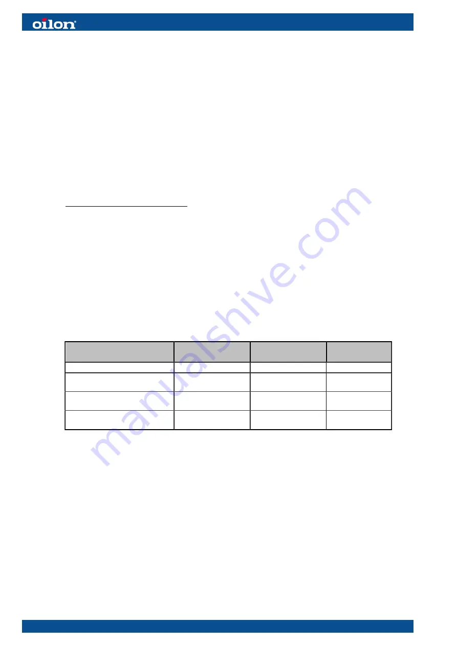
see the table below.
● If the compressor rotates in the wrong direction, stop the compressor
immediately by moving its motor protection circuit breaker (RE 28–48: F1; RE
56–96: 1F1) to the OFF position or by turning its operating switch to the OFF
position.
● If the compressor rotates in the wrong direction, make sure that the power
supply is de-energized and reverse the order of two phases in the heat pump’s
supply cable. After this, restart the process from the first step in this section.
● The unit is equipped with an internal phase guard. This device will stop the
compressor within 10 seconds of start-up, if the compressor rotates in the wrong
direction due to an incorrect phase order.
7. Check the temperature indicators to ensure that the condenser circuit starts to
warm up and the evaporator circuit to cool down.
Additional steps for RE 56–96:
1. Next, turn the lower unit’s operating switch S2 in the ON position.
2. Wait for the lower compressor to start.
3. The compressor will start with a delay depending on the system’s demand for
heating.
● If necessary, speed up the compressor’s start-up by using the outdoor
temperature simulation function and decreasing the cascade’s delay time and
degree minutes. Restore the settings after commissioning.
4. Make sure that the compressor rotates in the right direction.
● If the compressor rotates in the wrong direction, stop the compressor with
operating switch S2 or motor protection circuit breaker 2F1.
Identifying compressor rotation direction
Indication
Correct rotation
direction
Incorrect
rotation direction
Notes
Operating sound
Normal
Unusual
Hot gas pipe temperature (line
8415)
Increases
Does not increase
Line 8415
Pressure on the high pressure
side
Increases
Does not increase
Refrigerant gauge
pressure on the low pressure
(suction) side
Decreases
Does not decrease
Refrigerant gauge
4.3 Automation factory settings
RE 28–48
By default, the unit’s automation system has been configured for one domestic hot
water tank, one buffer tank for a heating circuit, and one heating circuit controlled by
a three-way valve. The automation system supports numerous other connections,
systems and accessories. Alternative system configurations are presented in separate
technical manuals for the automation system.
20 (74)
M8009 2147EN
Summary of Contents for RE 28 05
Page 1: ...M8009 2147EN 25 October 2021 Installation and operation manual RE 28 48 RE 56 96...
Page 2: ......
Page 45: ...RE 04 dimensions single unit configuration Two units M8009 2147EN 43 74...
Page 46: ...RE 04 dimensions two unit configuration 44 74 M8009 2147EN...
Page 61: ...7 4 EN 14285 Technical data sheets RE 28 RE 28 Technical data sheet ver 1 M8009 2147EN 59 74...
Page 62: ...RE 33 RE 33 Technical data sheet ver 1 60 74 M8009 2147EN...
Page 63: ...RE 38 RE 38 Technical data sheet ver 1 M8009 2147EN 61 74...
Page 64: ...RE 42 RE 42 Technical data sheet ver 1 62 74 M8009 2147EN...
Page 71: ...Wilo Stratos 40 1 12 Wilo Yonos MAXO 40 0 5 16 M8009 2147EN 69 74...
Page 77: ......


