PAGE 15
© 2018 OJ Electronics A/S
OJ Winterline
®
3 2 2 Sensors and Remote Control
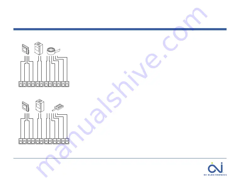
Connect the wires for the sensors and the remote control panel to the terminals
according to the type of sensors required in the system
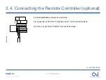
Remote Control Panel, ETOP-R (Optional)
Terminal 1: HMI - A
Terminal 2: HMI - B
Terminal 3: HMI - GND
Terminal 4: HMI - Supply (+28 VDC / 35 mA)
Sensors:
Terminal 5: Temp sensor 2 - GND
Terminal 6: Temp sensor 2 - Signal
Terminal 7: Temp sensor 1 - GND
Terminal 8: Temp sensor 1 - Signal
Terminal 9: Moisture sensor - Signal 1
Terminal 10: Moisture sensor - Signal 2
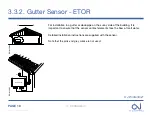
Terminal 11: Heating element in sensor ETOG/ETOR - GND
Terminal 12: -Heating element in sensor ETOG/ETOR - supply (+28 VDC / 125 mA)
BR1035A15 ©
2017 OJ Electronics
A/S
1 - 2
3 - 4
5 - 6
7 - 8 9 - 10 11 - 12
A
B
GND
+28V
Grey
Pink
Yellow
White
Brown
Green
Temp. sensor 1
Temp. sensor 2
Moisture sensor
Heating
ETOP-R
ETF
ETOG
BE1035A15
BR1035A16 ©
2017 OJ Electronics
A/S
1 - 2
3 - 4
5 - 6
7 - 8 9 - 10 11 - 12
A
B
GND
+28V
Yellow
White
Brown
Green
Temp. sensor 1
Temp. sensor 2
Moisture sensor
Heating
ETOP-R
ETF
ETOR
BE1035A16
>
<
Contents


