16
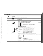
Err
or
indication
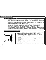
Flashing output LED (red):
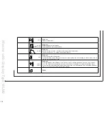
The appropriate output channel LED can flash, indicating that the room sensor or room contoller on that channel has a fault/error. The failure code can
also be seen in the service menu (submenu 2a).
E1, 1 flash
The master has lost communication to the room sensor. The fault is corrected by re-establishing the connection to the Room
Sensor and the fault condition will be automatically reset once correct communication is resumed. If the room sensor is
defective and has to be changed, or if it has been deliberately removed, it is necessary to make a HARD RESET. (NOTE: If the
room sensor is of the WIRELESS type, the error/fault message could be an indication that the power has failed, and that the
internal battery of the room sensor needs to be replaced)
E2, 2 flashes
The internal sensor in the room sensor/controller is defective. The fault can only be corrected by replacing the room sensor/
Controller. Remember to make a HARD RESET after installing the new room sensor/controller.
E3, 3 flashes
The limit sensor on the room sensor/controller is defective. Replace the faulty sensor. Reset is NOT required.
E4, 4 flashes
Defective WLCT2 room controller. If a room controller operating a group of room sensors becomes defective, the remaining
room sensors will continue control within the maximum and minimum limits programmed into the Room controller.
E5, 5 flashes
Two or more room controllers are trying to control this output. Check “AREA” setting on the room controllers.
E6, 6 flashes Channel output number one is configured as a dehumidifier output, error caused by a room sensor/controller also being set to
control this output.
RESET
There are 2 different reset actions that can be used.
HARD RESET
If the ‘
✓
’ button is pressed for 5 seconds, a HARD RESET will be initiated. (Indicated by all the red output LED’s(1-8) lighting in sequence). This reset
will remove from the system any room sensor unit with a defective input sensor, or a defective AO module. The fault message will be reset but the
defective items will no longer participate in the system. To add or replace a new unit, please refer to “Replacing equipment - Replacing a faulty sensor/
controller”. To erase the identity of the defective component from the master memory a HARD RESET must be performed Hard resets do not alter the
temperature settings already programmed into the master control.
FACTORY RESET
If the (
√
) button is pressed for more than 15 seconds, a total factory reset will be initiated. This is indicated through flashes of channel LEDs 1,3, 5 and
7 alternating with channel LEDs 2, 4, 6 and 8 (while the “
√
” button is pressed).
A factory reset will put all programmed temperature settings back to the factory defaults. It will also remove all room sensors/Controllers from the
master memory, and reset the system to accept only those room sensors/Controllers that are functioning correctly.
To reconnect room sensors/controllers, please refer to “Replacing equipment - Replacing a faulty sensor/controller”.
Summary of Contents for WLM2-1BA
Page 1: ...www oj dk User Manual WLM2 WLTA WLTD WLTP WLCT2 57640A 11 08 DJU...
Page 29: ...29...
Page 30: ...30...

