23
type W
lC
t
2
(and W
lC
t
2/
r
/HW/2)
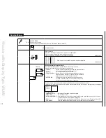
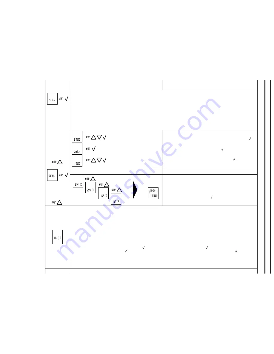
Hi li - Floor sensor. Max and min allowed temperature of the floor surface
A limit sensor can be connected to the room controller.
Max limitation
is used for safety to prevent high floor temperatures. For example wooden floor constructions which should not
be allowed to exceed a maximum of 27˚C. The value can be set from 5˚C up to 55˚C. The value can also be set to OFF (adjust the
temperature to 55˚C and push button up once more).
Low limitation
is used where the temperature of the floor is required never to fall below the minimum set temperature. Example in
kitchens or bathrooms with tiles. The value can be set from 5˚C up to 55˚C. The value can also be set to OFF (adjust the temperature to
5˚C and push button down once more). Remember the max limit temperature must be set higher than the min limit temperature.
The limit temperatures defined in the room controller will be valid for all the room sensors with limit sensor (type WLTD-19) which are part
of the area allocated to the WLCT2 unit.
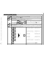
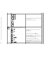
The maximum allowable floor temperature setting is shown. Use
the UP (
△
) or DOWN (
▽
) button to increase or reduce, and Ok ( )
button to accept.
The display will now show LoLi. Press Ok ( ) button to continue.
The minimum allowable floor temperature setting. Use the UP (
△
)
or DOWN (
▽
) button to increase or reduce and Ok ( ) button to
accept.
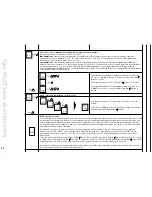
sCal - time and temperature scale selection
You can select either ˚C or ˚F scale, and 12 or 24 hour clock as
follows:
Press UP (
△
) or DOWN (
▽
) button to change settings. Confirm the
required scale with the Ok button ( ) button.
arEa - (group of rooms)
The rooms that are to be set as part of the WLCT2 area will follow the temperature settings of the room controller example, an area could
be the living room, kitchen, and children’s rooms, having a high room temperature requirement during afternoon and early evening, and
a lower temperature during the early part of the day and at night. Each room sensor will have a channel number, designated CH1, CH2
etc. The appropriate channel number of any room sensor is determined by the numbered output on the master control which is actually
switching the valve/actuator for that area.
For example, a system may have the kitchen room sensor operating master output # 4, and the childrens room sensor operating
master output #5. If the WLCT2 room controller is then situated in the living room, and operating output #1, then the WLCT2 need
be programmed to control outputs 1, 4, & 5. (Each room sensor will have been set to operate its appropriate output ch see separate
instructions).
To do this, enter the ArEA sub menu., and press Ok ( ) button. CH 1 will be displayed; use the Ok ( ) button and then the UP (
△
) button
to change the setting to ON. Press Ok ( ) and CH 2 is displayed. Use the UP (
△
) button until CH4 is displayed, press Ok ( ), and change
to ON. Repeat this for CH 5. All three room sensors will now operate under the control of the WLCT2 room controller.
In total up to 14 Channels can be programmed in this way, and it is possible to have more than a single room controller, each own sub
room sensors operating to its schedule and temperatures.
Summary of Contents for WLM2-1BA
Page 1: ...www oj dk User Manual WLM2 WLTA WLTD WLTP WLCT2 57640A 11 08 DJU...
Page 29: ...29...
Page 30: ...30...

